Virtual array failover

a virtual array and failover technology, applied in the field of storage systems, can solve the problems of increasing complexity of storage systems used for storage of data, inability of other hosts to access storage groups, and high cost of current methods for partitioning storage arrays into virtual arrays

Active Publication Date: 2007-12-06
EMC IP HLDG CO LLC
View PDF16 Cites 44 Cited by
  • Summary
  • Abstract
  • Description
  • Claims
  • Application Information

AI Technical Summary

Problems solved by technology

Ever larger and more complex storage systems are used for storage of the data.
Other hosts cannot access a storage group to which they have not been granted access.
Unfortunately, the current methods for partitioning storage arrays into virtual arrays are highly complex and expensive, and operate only at the storage array level.

Method used


Image

  • Virtual array failover
  • Virtual array failover
  • Virtual array failover

Examples


first embodiment

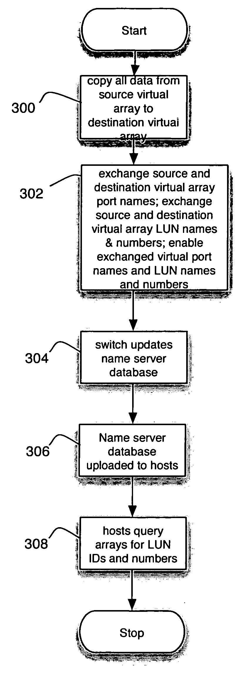
[0083] The general process by which a migration occurs from the source virtual array 210f to the destination virtual array 210i in a manner transparent to the hosts 12 in accordance with the first embodiment is shown in FIG. 17. First, the data is copied from the source array 210f to the destination array 210i (step 300). Then, the virtual array port names for the source virtual array 210f are exchanged with the virtual port names for the destination virtual array 210i, and, the source virtual array 210f LUN names and numbers are exchanged with the destination virtual array 210i LUN names and numbers. The exchanged virtual port names and LUN names and numbers are then enabled (step 302). Once the virtual port name and LUN name and number exchanges are complete, the switch 14a notes the configuration change and updates its name server database 40a in response (step 304). The hosts upload the updated name server database 40a (step 306). The hosts then query the presented virtual array...

second embodiment

[0103] In accordance with the second embodiment, it may be advantageous to simply copy the source virtual array data to the destination virtual array, and then replace the destination virtual array port names and LUN names and numbers with the source virtual array LUN names and numbers. In this case, after the link bounce, the destination virtual array appears as the source virtual array, and the source virtual array either disappears or is reinitialized as a new virtual array. One example of such an implementation is shown in FIGS. 32-35. In FIG. 32, an example of the general operation of the migration process is shown. FIG. 32 differs from FIG. 17 in that step 302 has been replaced with step 339. Rather than exchanging virtual port names and LUN names and numbers, destination virtual port names and LUN names and numbers are replaced with source virtual port names and LUN names and numbers. In FIG. 33, one possible example of alternate operation of the source array controller 44c i...


PUM


Abstract

Failover is provided between groups of logical units of storage presented as virtual arrays. A primary virtual array has at least one primary virtual port coupled to a fabric, each primary virtual port having a source virtual port name and a source virtual port address. A secondary virtual array has one or more secondary virtual ports coupled to the fabric, each secondary virtual port having a secondary virtual port name and a secondary virtual port address. All data resident on the primary virtual array is copied to the secondary virtual array. If a failure occurs in the primary virtual array, the secondary virtual port names and LUN names and numbers are replaced with the primary virtual port names and LUN names and numbers. The fabric then updates its name server database so that the database associates the primary virtual port names and LUN names and numbers with the secondary virtual port addresses.

Description

FIELD OF THE INVENTION [0001] The present invention relates generally to the field of storage systems, and particularly to the migration of data between virtual arrays. BACKGROUND OF THE INVENTION [0002] Today's enterprise data centers store ever-larger amounts of business critical data that must be immediately and continuously available. Ever larger and more complex storage systems are used for storage of the data. Many different hosts and applications access data on these storage systems. In order to provide security and prevent data corruption, it is often necessary to ensure that the applications and hosts have exclusive access to particular areas of storage in the system. [0003] One mechanism for partitioning storage systems employs the concept of “virtual arrays”. Accordingly, software is provided within a storage array to logically partition the array into separate storage groups. Each storage group includes at least one host and a set of logical units of storage. The logical...

Claims


Application Information

Patent Timeline
Patent Type & Authority Applications(United States)
IPC IPC(8): G06F11/16G06F12/08
CPCG06F3/0617G06F3/0647G06F3/067G06F11/2097G06F11/2082G06F11/2094G06F11/1662
Inventor MADNANI, KIRANOFER, ADIBROWN, JEFFREY A.
Owner EMC IP HLDG CO LLC
Why Eureka
Try Eureka