Quick change over apparatus for machine line

a technology of machine line and apparatus, applied in the direction of forging/pressing/hammering apparatus, forging tools, forging presses, etc., can solve the problems of total inaccessibility to operators and considerable downtime, and achieve the effect of reducing the number of operations/tim

Active Publication Date: 2007-12-13
BELVAC PRODN MACHINERY
View PDF10 Cites 16 Cited by
  • Summary
  • Abstract
  • Description
  • Claims
  • Application Information

AI Technical Summary

Benefits of technology

[0008] In order to quickly change over from the production of one type of can to another wherein the new can features one or more of a different diameter, length, neck profile, the machine line which comprises a series of turret machines incorporates apparatus (devices / arrangements) which reduce the number of operations / time necessary to condition the line to the degree that a new set up is achieved.
[0009] For example, in order to accommodate a can having a different length, either the turret which is configured to carry the rams which carry / drive the push plates, or the turret which carries the dies / knockout rams, is arranged to be movable with respect to the corresponding turret which carries the other of the push plate / rams, and dies / knockout rams. This allows the movable turret to be moved toward or away from the other (the stationary turret) to allow for the difference in length and obviates the need to change each of the push plates to allow for the different length can. This immediately reduces 10-16 time consuming operations per turret machine.

Problems solved by technology

However, a drawback is encountered when switching from a run of one sized can to another, in that the downtime tends to be considerable.
The close proximity of the turrets and the serpentine path along which the cans are conveyed, introduces problems such that, merely by way of example, when it is necessary to change over the dies, only two or three of these dies are accessibly exposed at the top of the turret on which they are supported, the remaining dies remaining between or below the turrets and thus totally inaccessible to an operator.
This of course is inevitably carried out by hand.

Method used


Image

  • Quick change over apparatus for machine line
  • Quick change over apparatus for machine line
  • Quick change over apparatus for machine line

Examples


Embodiment Construction

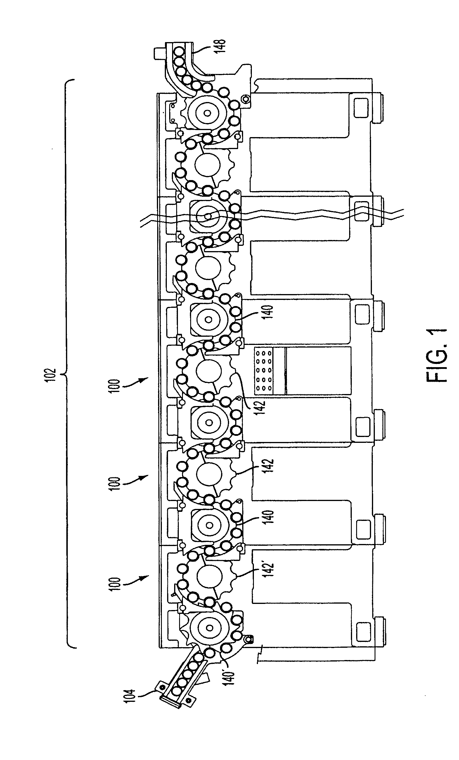
[0084]FIG. 1 shows in schematic elevation, the basic path followed by the cans as they are necked as they pass through a series of turret necking machines which comprise which shall be referred to as a “machine line 102” and in which the various embodiments of the invention are incorporated. In this embodiment, the path is essentially serpentine in configuration.

[0085] As shown, the cans enter the line via a can infeed 104 and are picked up by a first transfer starwheel 140′. The cans which are held in position on this first transfer starwheel 140′ using a pneumatic pressure differential or “suction” as it will be referred to. Further disclosure of this first starwheel will given hereinlater.

[0086] The cans are then passed from the first transfer starwheel to a first turret starwheel 142′ and enter into the first stage of necking on the first necking machine 100. While the invention is not so limited, embodiments of the invention are such that necking machines 100 are constructed ...


PUM

PropertyMeasurementUnit
speedaaaaaaaaaa
diameteraaaaaaaaaa
lengthaaaaaaaaaa

Abstract

A machine arrangement includes a plurality of machines arranged to cooperate with each other in a manner which comprises a machine line. This machine line incorporates apparatus which is associated with and / or comprises part of the machines for: at least one of moving, holding, manipulating and shaping cans as they pass from a can infeed to a can discharge of the machine line and move along a path having a predetermined configuration. This apparatus minimizes operations necessary for changing from a set up suitable for modifying a can having a first set of dimensions to a set up suitable for a can having a second set of dimensions.

Description

[0001] This application is a Divisional of U.S. application Ser. No. 11 / 126,151, filed May 11, 2005, which claims priority to Provisional Application No. 60 / 628,562 filed Nov. 18, 2004. The entire content of the aforementioned applications are incorporated herein by referenceFIELD OF THE INVENTION [0002] The present invention relates generally to series of machines or machine units which constitute a machine line, and more specifically to apparatus which forms part of the machines and which enables the line to be quickly switched between a first set-up wherein a first sized product is modified / manufactured and at least one other set-up wherein a different dimensioned product is modified / manufactured. BACKGROUND OF THE INVENTION [0003] Necking machines have been used to form the neck on beer and beverage cans and the like for some time. These machines have evolved to the degree that reliable high speed precision necking is reliably realized. However, a drawback is encountered when sw...

Claims


Application Information

Patent Timeline
Patent Type & Authority Applications(United States)
IPC IPC(8): B23B7/04
CPCB21D51/2615Y10T29/5154B21D51/2692
Inventor SCHILL, JOSEPH G.SHORTRIDGE, JEFFERY L.SHUEY, CHRISTOPHER D.GREEN, DENNIS E.
Owner BELVAC PRODN MACHINERY
Why Eureka
Try Eureka