Hydraulically locked boat accessory mounting device

a technology of hydraulic locking and accessory mounting, which is applied in the direction of special-purpose vessels, vessel construction, couplings, etc., can solve the problems of boat, its accessories, boat, and its vibration, and achieve the effect of facilitating the repositioning of accessories and minimizing the use of tools

Inactive Publication Date: 2007-12-13
J & J MACHINE & TOOL
View PDF13 Cites 9 Cited by
  • Summary
  • Abstract
  • Description
  • Claims
  • Application Information

AI Technical Summary

Benefits of technology

[0017]The accessory mounting device allows accessories to be attached to a boat in a desired, selected position or orientation. Because a boat is operated upon water, it is desirable to have equipment that is captive or otherwise has no removable parts, which are susceptible to being dropped overboard. It is also desirable to minimize the use of tools, which can be dropped overboard. The hydraulic locking assembly allows for easy repositioning of accessories without removing any parts or using any tools.

Problems solved by technology

Additionally, boats are subject to vibration.
Not only is the boat, and its accessories, exposed to the vibration from the engine as it runs at various speeds and power levels, but the boat is also subject to vibration, shocks, and impacts as it moves through and / or over the water at various speeds.
Unfortunately, when working with fasteners and tools, the fasteners and / or tools are often dropped.
On a boat, which is normally floating on water, dropping a fastener or tool results in a loss of that fastener or tool if it ends up in the water.
Many of the prior art devices do not exhibit sufficient strength to support heavy marine accessories and / or are not self-contained.

Method used


Image

  • Hydraulically locked boat accessory mounting device
  • Hydraulically locked boat accessory mounting device
  • Hydraulically locked boat accessory mounting device

Examples


Embodiment Construction

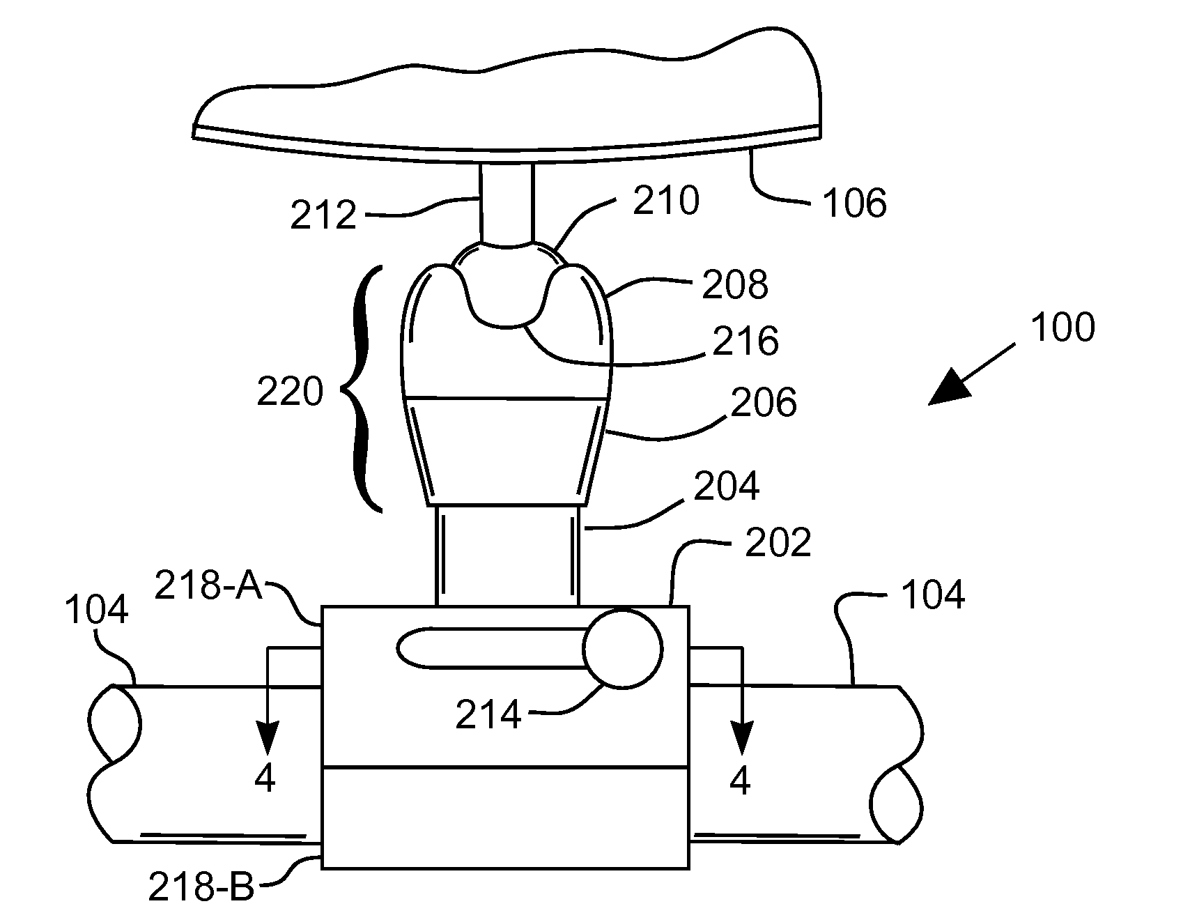
[0027]An apparatus for a hydraulically locked accessory mounting device is disclosed. Boat owners and operators oftentimes wish to mount accessories onto their vessels. These accessories often require positioning to achieve proper or optimum functionality. Further, it is desirable to position such accessories without removing equipment or parts and without using tools. Boat accessories include many items that are attached to a boat 102, including speakers, mirrors, towers, lights, and racks for wakeboards, skies, life preservers, and / or personal floatation devices.

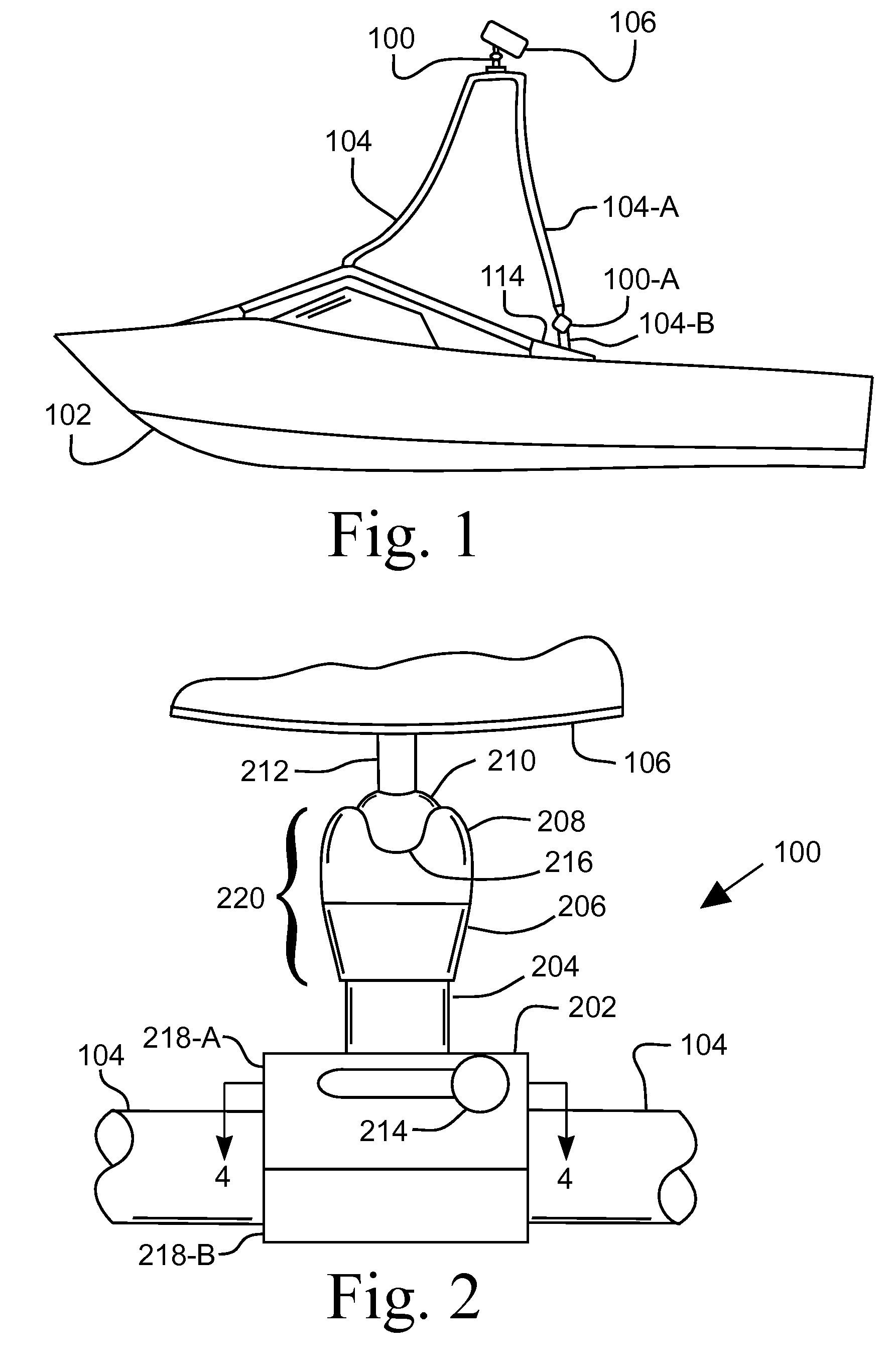
[0028]FIG. 1 illustrates a side view of a vessel 102 showing an accessory mounting device 100 attached to a tower 104 and supporting a speaker 106. The speaker 106 is illustrated with its aft, or rearward facing, end aimed downward toward the aft cockpit of the boat 102. Such positioning is oftentimes a matter of preference of the boat operator in order to obtain optimum functionality of the accessory, which in the illustr...


PUM


Abstract

An apparatus for a hydraulically locked accessory mounting device for attaching accessories to a boat, or vessel. The mounting device includes a base for attaching to the boat and a ball head that is attached to an accessory, which can be moved to a selected position and locked in that position by a hydraulic assembly. The hydraulic assembly includes a first piston moved by an operator. The first piston is in hydraulic communication with a second piston, which engages a shoe that locks the ball in position. In one embodiment, the hydraulic system includes a bleed valve connected to the channel between the first and second pistons. In one embodiment, the first piston is operated by a knob with a threaded shaft. In another embodiment, the first piston is operated by a cam on a shaft that is rotated with a lever or knob.

Description

CROSS-REFERENCE TO RELATED APPLICATIONS[0001]Not ApplicableSTATEMENT REGARDING FEDERALLY SPONSORED RESEARCH OR DEVELOPMENT[0002]Not ApplicableBACKGROUND OF THE INVENTION[0003]1. Field of Invention[0004]This invention pertains to an accessory mounting device with a hydraulic locking assembly. More particularly, this invention pertains to a device for attaching a boat accessory, such as a light, speaker, rack, or mirror, to a rail or other member of a boat or other vessel. The attaching device has a ball joint that is locked in place with a hydraulic locking assembly.[0005]2. Description of the Related Art[0006]Marine vessels require various accessories in order to serve the needs of the vessel operators. For example, sport boats, which are one type of marine vessel, are often used to tow water skiers and / or wakeboarders. These boats require a mirror to allow the operator to view the person being towed while operating the boat. It is also often desired to outfit these boats with speak...

Claims


Application Information

Patent Timeline
Patent Type & Authority Applications(United States)
IPC IPC(8): B63B17/00
CPCB63B17/00F16C11/106F16M11/14Y10T403/32319Y10T403/22Y10T403/32311F16M13/02F16C2326/30
Inventor JACKSON, JOHN R.
Owner J & J MACHINE & TOOL
Why Eureka
Try Eureka