Gaming device

a technology of a gaming device and a battery, applied in the field of gaming devices, can solve the problems of increasing fatigue of players continuing the game, and achieve the effect of reducing player fatigu

a technology of a gaming device and a battery, applied in the field of gaming devices, can solve the problems of increasing fatigue of players continuing the game, and achieve the effect of reducing player fatigu

US20070284814A1Inactive Publication Date: 2007-12-13UNIVERSAL ENTERTAINMENT CORP

Image

  • Gaming device
  • Gaming device
  • Gaming device

Examples


Embodiment Construction

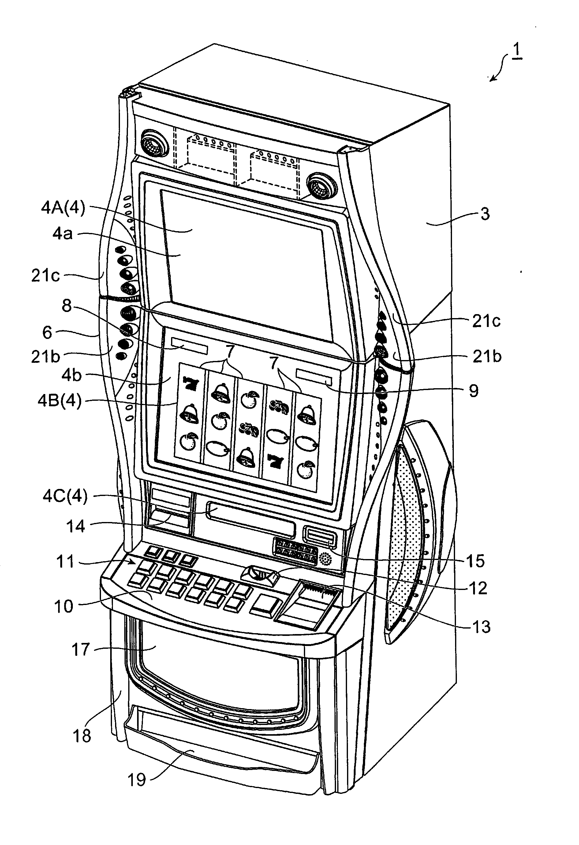
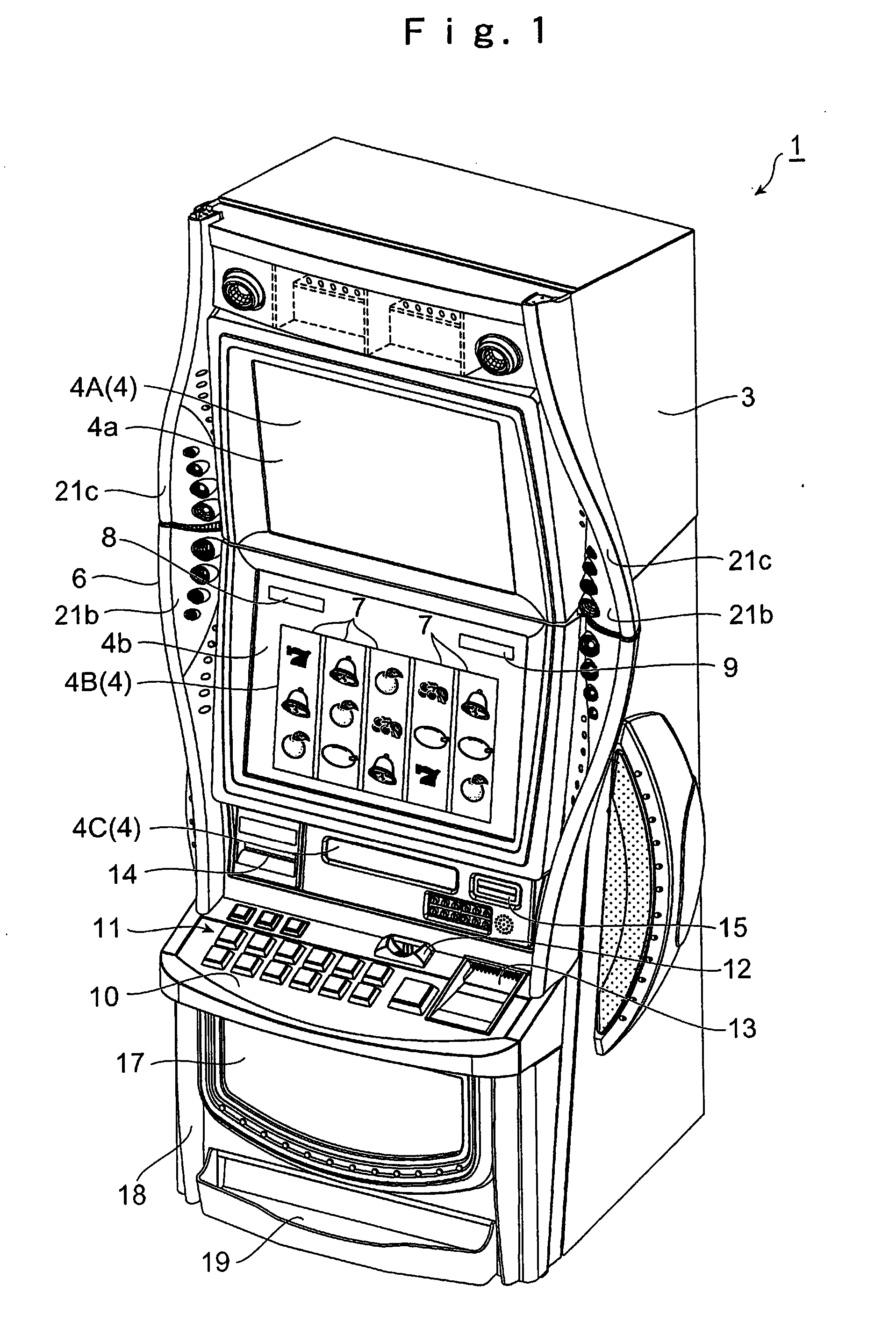
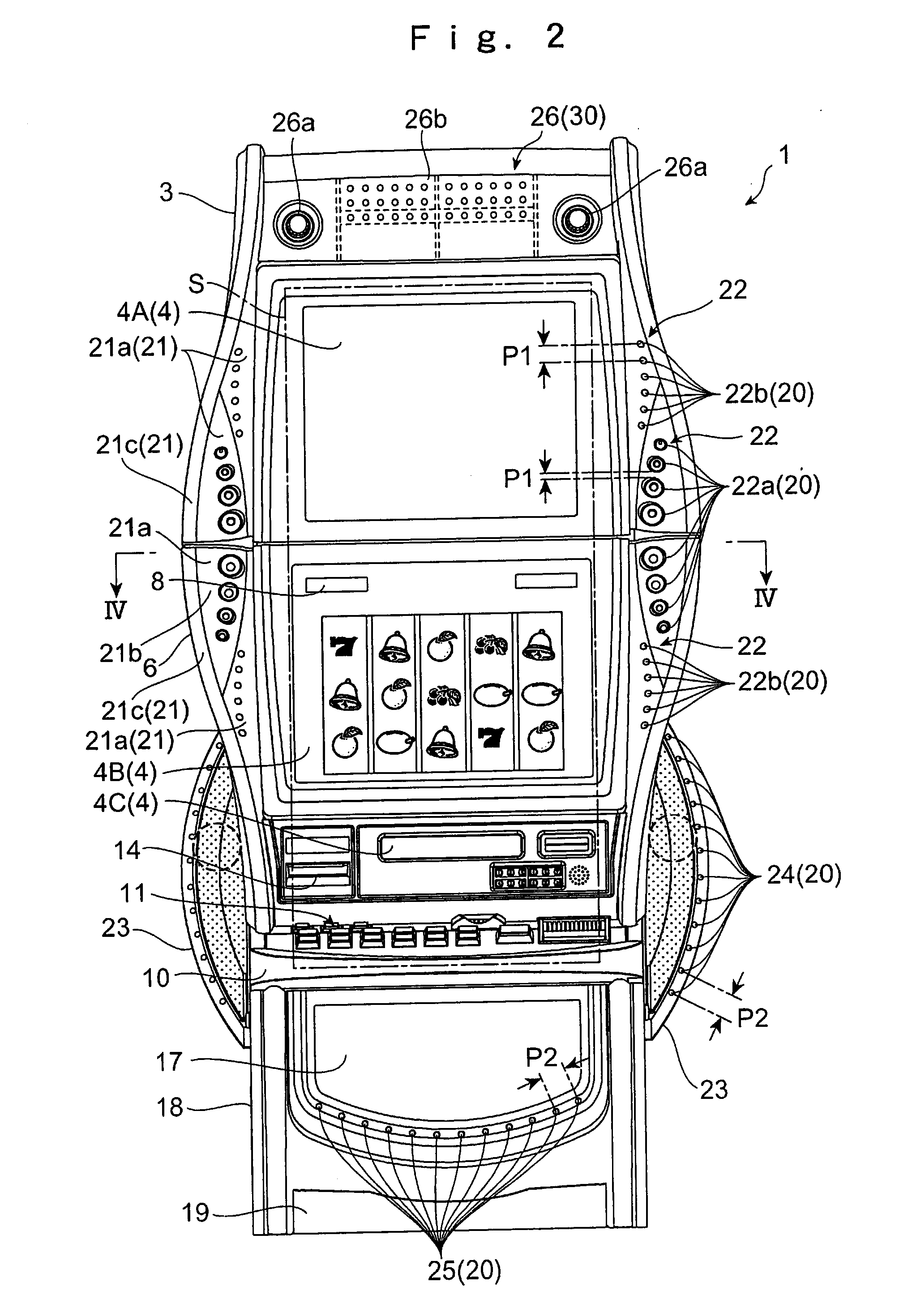
[0061] A gaming device according to the invention includes a cabinet having a display portion, which displays information relating to a game, and an operation portion for a player to carry out an operation of the game, a light emitting portion which emits light, and a light interception portion which intercepts at least some of light heading toward a player, from among light emerging from a light source provided on the light emitting portion.

[0062] In this kind of gaming device, at least some of the light heading toward the player, from among the light emerging from the light source of the light emitting portion, is intercepted by the light interception portion. For this reason, light from the light emitting portion entering the player's field of vision being reduced by the light interception portion, fatigue of a player continuing the game is reduced.

[0063] Also, it is preferable that the light emitting portion has a lens which converges the light emerging from the light source. ...


PUM


Abstract

To provide a gaming machine which achieves a reduction in a player's fatigue. A gaming machine 1 according to the invention includes a cabinet 3, having a display portion 4 which displays information relating to a game and operation buttons 11 for a player to carry out an operation of the game, a power lamp light emitting portion 300 which emits light, and a lens barrel 310 which intercepts at least some of light heading toward a player, from among light emerging from LED's 302 provided on the power lamp light emitting portion 300. In this kind of gaming machine 1, at least some of the light heading toward the player, from among the light emerging from the LED's 302 of the power lamp light emitting portion 300, is intercepted by the lens barrel 310. For this reason, light from the power lamp light emitting portion 300 entering the player's field of vision being reduced by the lens barrel 310, fatigue of a player continuing the game is reduced.

Description

RELATED APPLICATION [0001] This application claims the priority of Japanese Patent Application No. 2006-161655 filed on Jun. 9, 2006, which is incorporated herein by reference. BACKGROUND OF THE INVENTION [0002] 1. Technical Field [0003] The present invention relates to a gaming device applicable to a gaming machine, such as a slot machine, in which symbols aligned in a plurality of arrays are variably displayed. [0004] 2. Related Art [0005] To date, a gaming machine (for example, a slot machine or the like) which, by causing a revolving reel (a variable display device), on a perimeter of which a symbol array is provided, to revolve, carries out a game variably displaying symbols has been known. As the variable display device installed in this kind of gaming machine, one which varies the symbols by mechanically revolving an actual revolving reel, and one which variably displays the symbols by simulating a revolution of the revolving reel on an image display device such as a liquid c...

Claims


Application Information

Patent Timeline
13 Dec 2007
Publication
US20070284814A1
IPC
G07F17/32; A63F9/24; A63F5/04
CPC
G07F17/3211; G07F17/3202
Inventors
HIRATO, JUN; TANABE, YASUAKI