Printer system and control method thereof

Inactive Publication Date: 2007-12-13
CANON KK
View PDF2 Cites 12 Cited by
  • Summary
  • Abstract
  • Description
  • Claims
  • Application Information

AI Technical Summary

Benefits of technology

[0008]The present invention provides a printer system and a control method thereof that are capable of reducing wasteful power consumption by apparatuses

Problems solved by technology

If a plurality of loads are simultaneously started upon start of, e.g., a printer job, a problem is caused that the capacity of power source is deficient compared with a large electric current required for the starting operation.
Howe

Method used


Image

  • Printer system and control method thereof
  • Printer system and control method thereof
  • Printer system and control method thereof

Examples


Example

First Embodiment

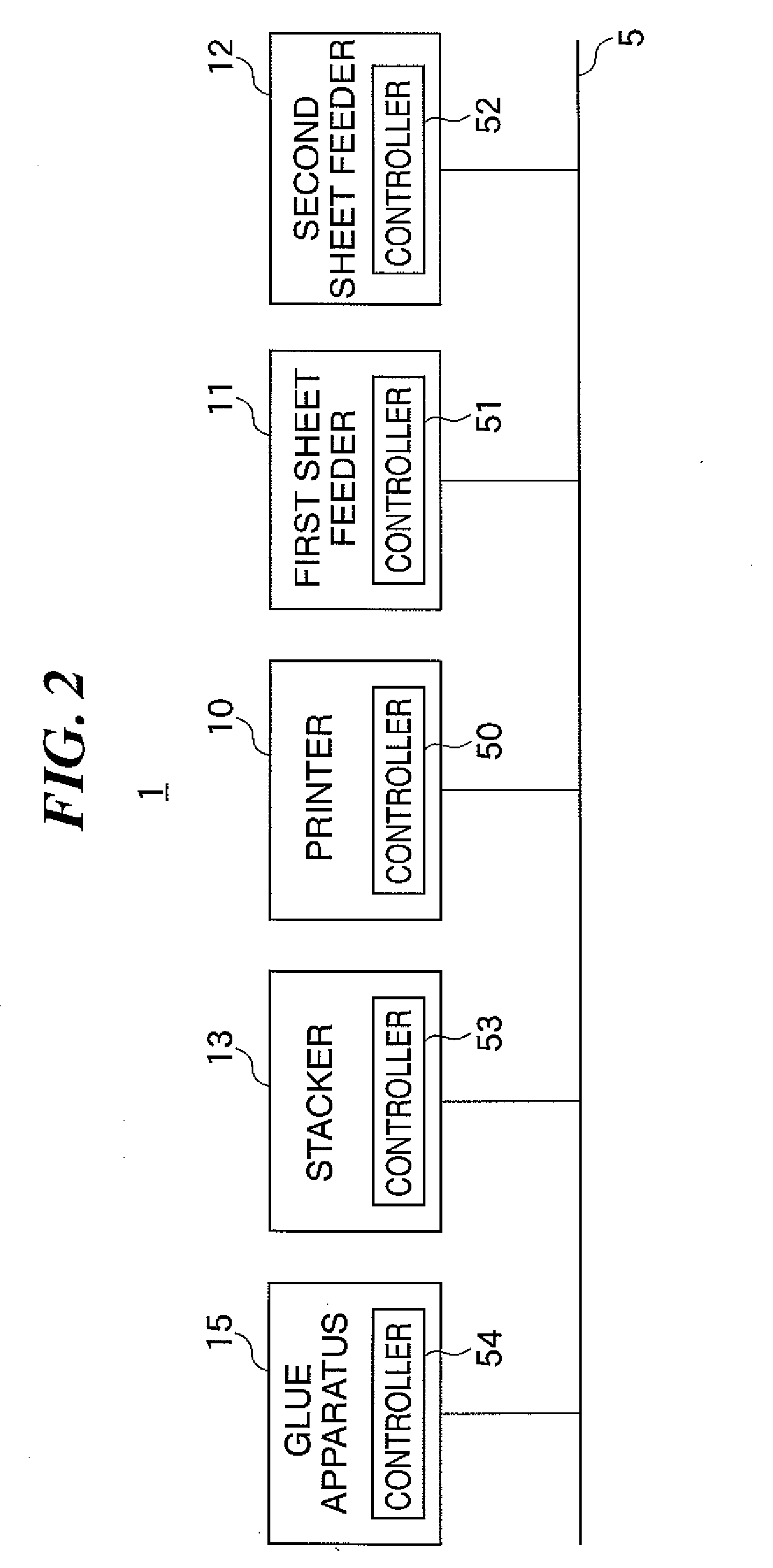
[0038]FIG. 1 is a block diagram exemplarily showing the construction of a printer system according to a first embodiment of the present invention, and FIG. 2 is a block diagram showing an example of the arrangement in which part of the construction of the printer system in FIG. 1 is modified.

[0039]Referring to FIG. 1, a printer system 1 is comprised of a printer 10 (image forming apparatus) that forms an image on a sheet, a plurality of sheet feeding decks (first and second sheet feeders 11 and 12) from which various sheets are fed to the printer 10, a stacker 13 on which sheets discharged from the printer 10 are stacked, and a stapler 14 that staples sheets discharged from a sheet discharge mechanism of the stacker 13.

[0040]On the other hand, a printer system 2 has a glue apparatus 15 instead of the stapler 14 of the printer system 1 shown in FIG. 1.

[0041]The apparatuses of the printer system 1 and the glue apparatus 15 comprise, as control means, controllers (contr...

Example

Second Embodiment

[0071]Next, a printer system according to a second embodiment will be explained. The printer system of the second embodiment is the same in construction as that of the above described first embodiment, and therefore an explanation on different points therebetween will be given below, with explanations on structural elements denoted by the same reference numerals omitted.

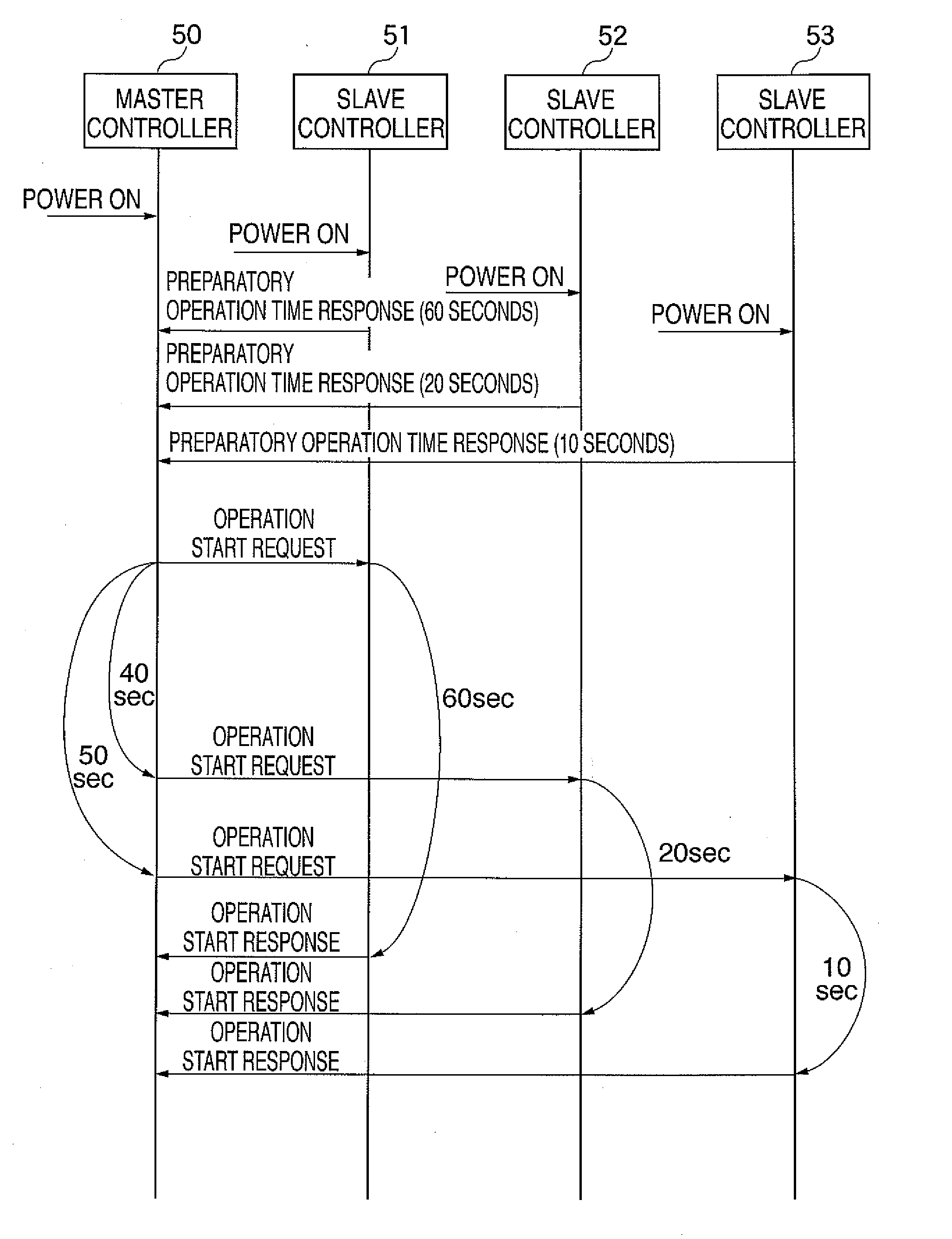
[0072]FIG. 10 is a sequence chart exemplarily showing communication between a master controller and a plurality of slave controllers in the printer system according to the second embodiment.

[0073]When power is turned on by a power switch, not shown, and a job start request is supplied from an operating panel, not shown, to the master controller 50 in the printer 10, the master controller 50 transmits operation preparation time requests to the slave controllers 51 to 53.

[0074]When receiving operation preparation time requests from the master controller 50, the slave controllers 51 to 53 start calculat...

Example

Third Embodiment

[0086]Next, a printer system according to a third embodiment will be explained. The printer system of the third embodiment is the same in construction as that of the above described first embodiment. Thus, an explanation on different points will be given below, with explanations on structural elements denoted by the same reference numerals omitted.

[0087]FIG. 13 is a sequence chart exemplarily showing communication between a master controller and a plurality of slave controllers in the printer system according to the third embodiment.

[0088]When power is on by a power switch, not shown, and a job start request is supplied from an operating panel, not shown, to the master controller 50 in the printer 10, the master controller 50 transmits operation preparation time requests to the slave controllers 51 to 53.

[0089]When receiving operation preparation time requests from the master controller 50, the slave controllers 51 to 53 start calculating preparatory operation times ...


PUM


Abstract

A printer system capable of reducing wasteful power consumption by apparatuses forming the printer system and preventing the service lives of the apparatuses from being shortened and capable of optimizing the capacity of power source. When power of the apparatuses of the printer system is on, a slave controller of each apparatus calculates a preparatory operation time of the apparatus, and transmits the calculated preparatory operation time to a master controller. Based on preparatory operation times indicated by data received from the slave controllers, the master controller determines start-up commencement times (start-up timings) of the slave controllers, and requests (instructs) the slave controllers to start operations upon elapsed of the determined start-up commencement times. In response to received operation start requests, the slave controllers start preparatory operations.

Description

BACKGROUND OF THE INVENTION[0001]1. Field of the Invention[0002]The present invention relates to a printer system including an image forming apparatus such as an electrophotographic printer and a plurality of sheet processing apparatuses such as finishers connected to the image forming apparatus via communication means, and relates to a control method of the printer system. More specifically, the present invention relates to a method for determining a start-up sequence in which apparatuses in the printer system are started.[0003]2. Description of the Related Art[0004]As shown by way of example in FIG. 1, a printer system is comprised of apparatuses such as a printer 10 for forming an image on a sheet, a plurality of sheet feed decks (first and second sheet feeders 11, 12) for feeding sheets to the printer 10, a stacker 13 for stacking thereon sheets discharged from the printer 10, and a stapler 14 for stapling sheets discharged from the stacker 13. These apparatuses forming the prin...

Claims


Application Information

Patent Timeline
IPC IPC(8): G06F3/12
CPCG03G15/5004
Inventor YAMAMOTO, SATORUMATSUMOTO, HIROSHI
Owner CANON KK
Why Eureka
Try Eureka