Tire rasp drawknife and mounting therefore

a drawknife and tire technology, applied in the field of tire retreading, can solve the problems of lowering the operative safety, large collision force, and low efficacy of conventional drawknife, and achieve the effect of low effect of conventional drawkni

a drawknife and tire technology, applied in the field of tire retreading, can solve the problems of lowering the operative safety, large collision force, and low efficacy of conventional drawknife, and achieve the effect of low effect of conventional drawkni

US20070286690A1Inactive Publication Date: 2007-12-13PEREZ RICARDO DANIEL

Image

  • Tire rasp drawknife and mounting therefore
  • Tire rasp drawknife and mounting therefore
  • Tire rasp drawknife and mounting therefore

Examples


Embodiment Construction

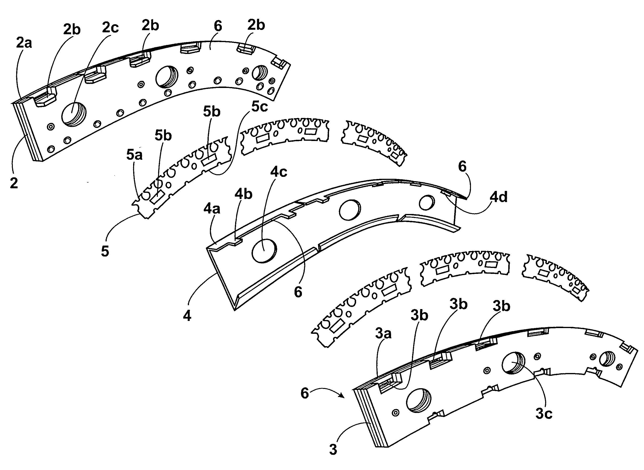
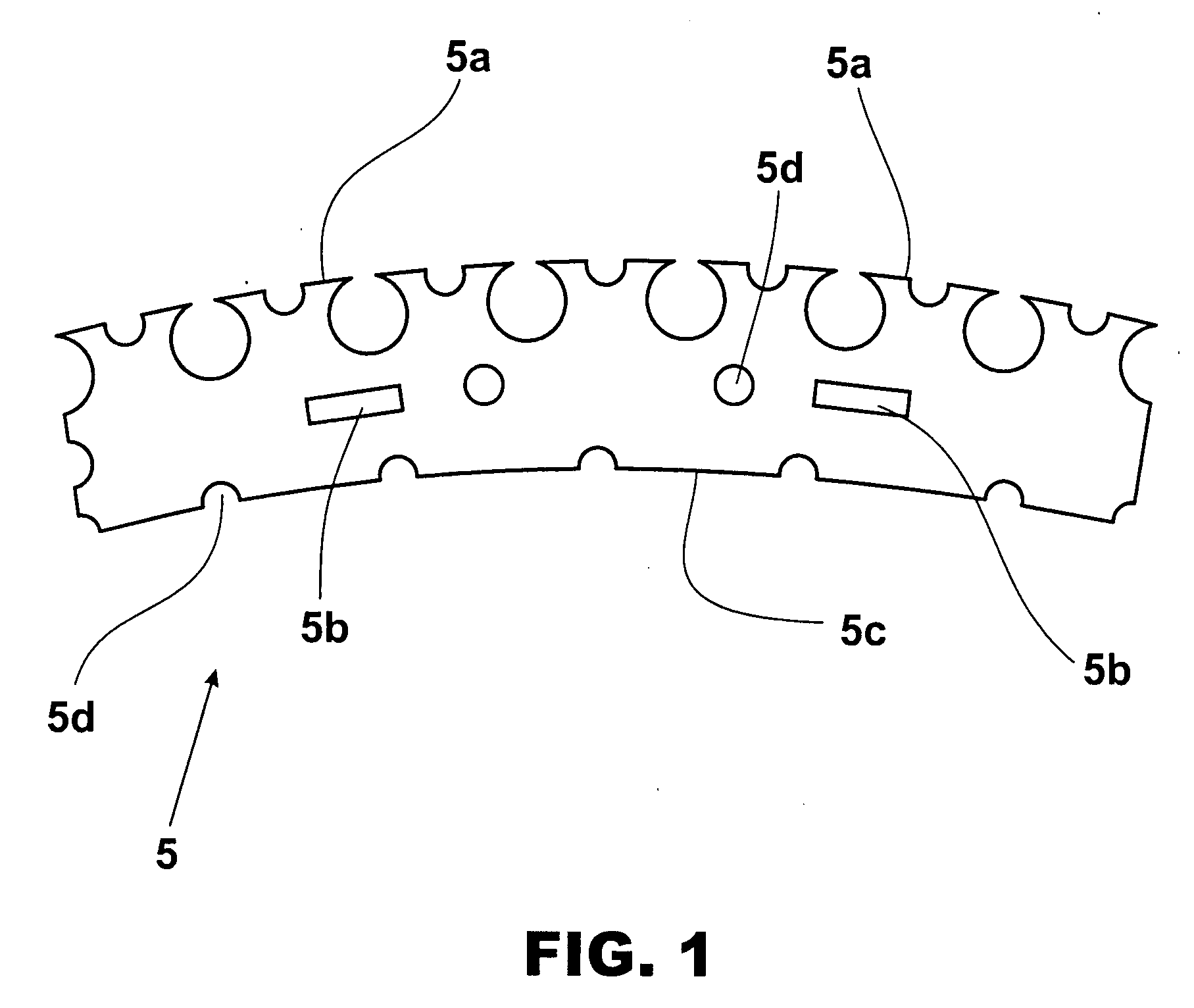
[0068]More particularly, the present mini drawknife or rasp blade (5) comprises a body or notched blade, which notched rim (5a) produces the superficial roughing of the tie tread (31) (30) that is to be treaded later.

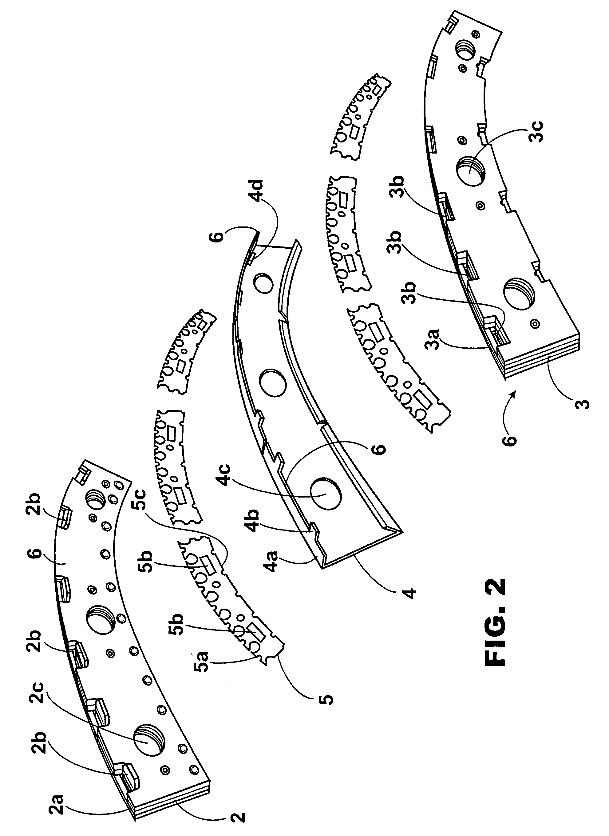
[0069]This mini drawknife (5) or notched blade more appropriate for the present device has a body that, from the notched rim (5a), extends briefly all across until reaching such a width that the opposite rim (5c) to the notched rim (5a) does not interfere with the openings (2c)(3c)(4c) and assembly bolts (20c) in the support (20).

[0070]However, the width of the drawknife (5) is enough to be inserted among the parts (2)(3)(4) of the fastening set (1), at the point where the fastening members are placed (2b)(4b). The latter can go through the body of the drawknives (5) thanks to the presence of third fastening openings (5b). In this manner, the drawknives (5) remain firmly and immovably fastened by the fastening set (1).

[0071]For the purpose of saving material and reducin...


PUM


Abstract

The mini drawknife body has one or more fixing openings which allow its assembly in the adjacency of the support periphery; from the notched rim, the body extends briefly right across until reaching such a width that the rim opposite to the notched rim cannot interfere with the openings and assembly bolts on the support. The invention also refers to an adaptation device for the assembly of the mini drawknife in a rotary support for tires roughing. This adaptation device comprises fixing sets integrated by bases and lateral retaining covers, among which intermediate separators can be placed; all these means have fixing members and openings which, in addition to forming jaws in the joint area, fasten to the roughing drawknives passing through some fastening openings of their body.

Description

FIELD OF THE INVENTION[0001]This application claims the benefit of Argentina Patent Application No. P20060102471, filed Jun. 12, 2006, and Argentina Patent Application No. P200701-1674, filed Apr. 18, 2007.[0002]The present invention refers to the field of different industrial techniques related to the work with plastic materials, particularly with tire retreading.[0003]More particularly, it consists of a mini drawknife of peripheral assembly for superficial roughing which body is prepared to prevent the interference with the support bolts and for the assembly on the adjacency of the periphery of the supports by means of adaptation devices.[0004]The invention also refers to an adaptation device of the assembly of the mini drawknife which fastening sets allow fastening the roughing drawknives firmly in the peripheral sector of the support.PRIOR ART[0005]It is known that retreading is a process through which a worn out tire is renewed by means of placing a new tread on it. The purpose...

Claims


Application Information

Patent Timeline
13 Dec 2007
Publication
US20070286690A1
IPC
B23D71/00
CPC
B23D71/005; B23D71/025; Y10T407/181; B29D2030/541; Y10T407/1815; B24B5/366
Inventors
PEREZ, RICARDO DANIEL