Apparatus and Method for Controlling Image Coding Mode

Inactive Publication Date: 2007-12-20
SANYO ELECTRIC CO LTD
View PDF4 Cites 24 Cited by
  • Summary
  • Abstract
  • Description
  • Claims
  • Application Information

AI Technical Summary

Benefits of technology

[0028] By employing the structure such as this, even if, at the time of coding a targeted frame in the inter-frame bidirectional predictive mode, a future reference frame is a copy of a past reference frame, difference data relative to a reference frame can be provided, for example, instead of being processed automatically as a copy of the past reference frame. Thereby, the loss of image can be prevented and the image quality of decoded images can be enhanced.
[0029] When the coding method decision unit determines that the block in the frame to be coded shall not be processed as the copy of a prescribed block of a frame of the past reference frame, the coding unit may code difference data between the prescribed block of the past reference frame and the block in the frame to be coded. Thereby, the image of the targeted frame can be obtained by

Problems solved by technology

Thus, various constraints according to their execution environments i

Method used


Image

  • Apparatus and Method for Controlling Image Coding Mode
  • Apparatus and Method for Controlling Image Coding Mode
  • Apparatus and Method for Controlling Image Coding Mode

Examples


first embodiment

Embodiment 1

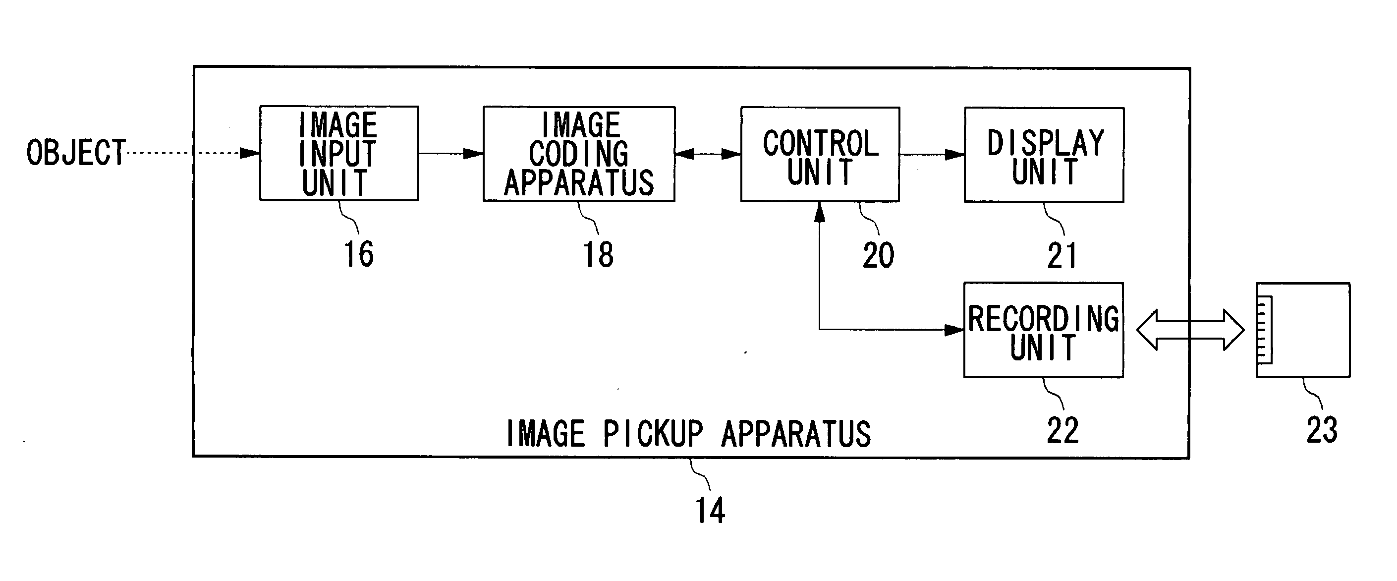
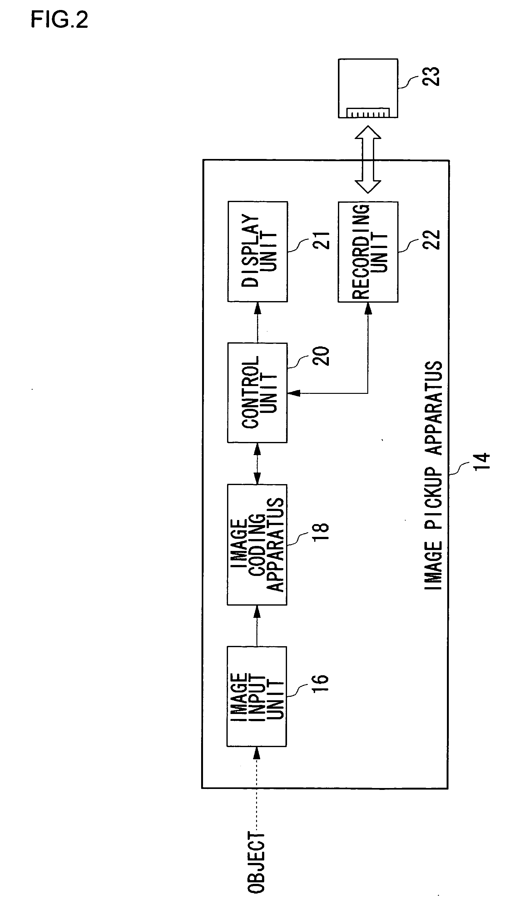
[0062] An image coding apparatus and an image pickup apparatus according to the present embodiment are realized as a circuit for the coding and a digital camera including said circuit. This circuit for the coding selects a reference mode for image coding according to a resolution setting for an image shot by the digital camera. More specifically, a reference mode with a smaller processing load is selected at high-resolution capturing whereas a reference mode with a higher processing load is selected at non-high-resolution capturing. When this is made into a structure such that a single reference mode only is used, the selection of a reference mode must be designed in accordance with the high-resolution capturing, so that the compression ratio or image quality cannot be given the priority until such a time for non-high-resolution capturing. According to the present embodiment, the high compression ratio and high quality of image can be achieved at the time other than the...

embodiment 2

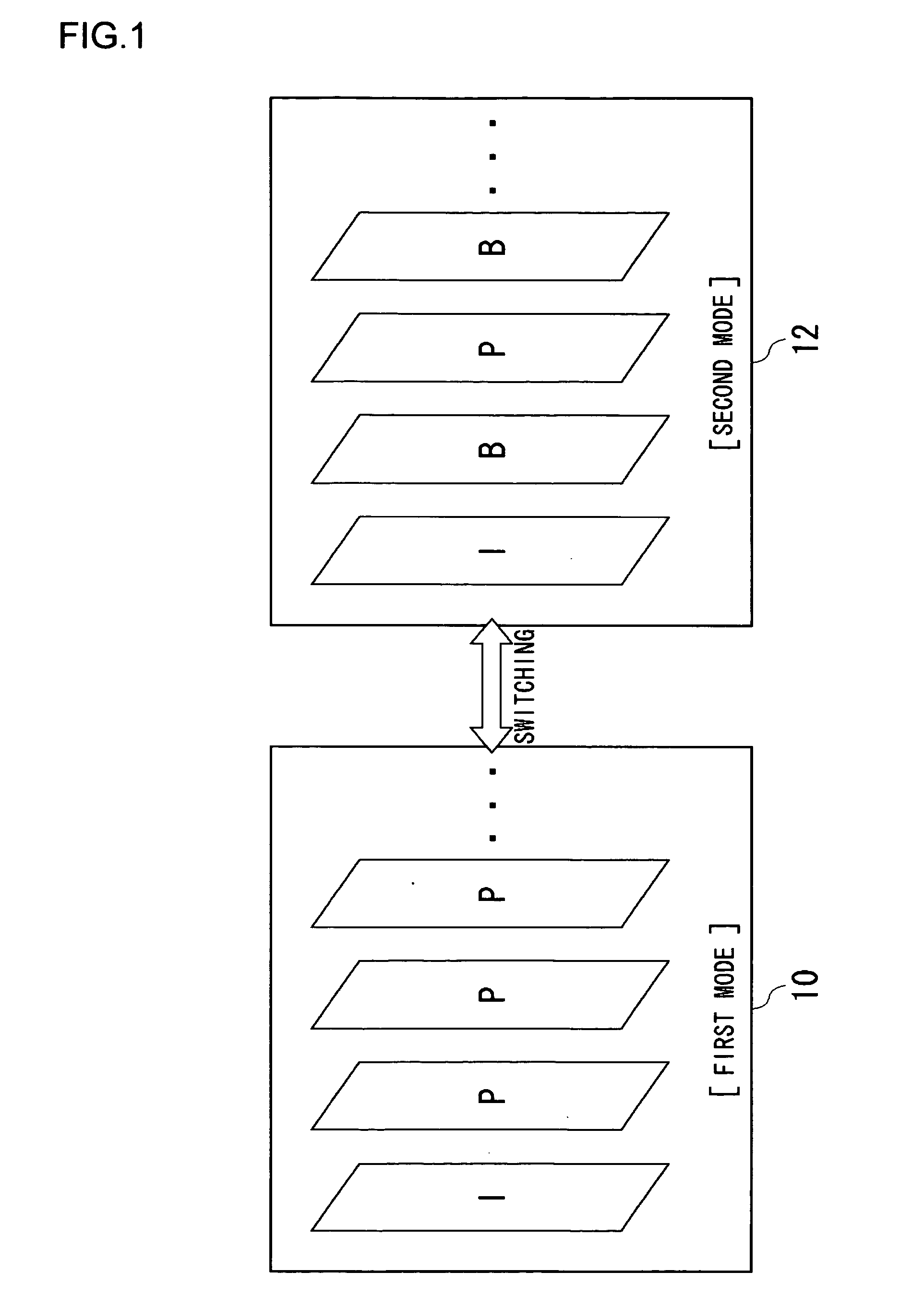
[0073] An image coding apparatus and an image pickup apparatus according to the present embodiment differs from Embodiment 1 in that the reference mode for image coding is selected, as an execution environment for the coding processing, according to the setting of a frame rate for an image to be captured. More specifically, the reference mode in which the bidirectional coding is used with the priority given to high compression ratio and image quality is selected at high frame-rate capturing. If, on the other hand, the frame rate is too low, there will be cases where the motion vector cannot be detected because the intervals from the preceding and subsequent frames are too large. Hence, the bidirectional referencing might rather cause the image quality to degrade. In the light of this, the reference mode in which the bidirectional coding is not used is selected at a low frame rate. Here, in a case where a structure is implemented such that a single reference mode only is used, the se...

embodiment 3

[0076] An image coding apparatus according to the present embodiment shares the same feature as with the Embodiment 1 in that the reference mode is selected, as an execution environment for the coding processing, according to the resolution setting for images to be captured. Although the reference mode in which the bidirectional coding is used is selected, at high-resolution capturing, with the priority given to the high compression ratio and image quality, there is a possibility that the compression ratio and image quality is raised to a level more than necessary if the bidirectional coding is used at low-resolution capturing. In the light of this, the reference mode in which the bidirectional coding is not used is selected, at low-resolution capturing, with the priority given to the processing speed and the load reduction. If a structure is implemented such that a single reference mode only is used, the selection of a reference mode must be designed in accordance with either the h...


PUM


Abstract

As result of the diversified structure of a terminal device, the demand for data format is also diversified and there is a need to adjust a terminal to such a demand. An image coding apparatus according to the present invention uses a method complied with MPEG, as a method by which to code images, and particularly uses intra-frame coding and inter-frame coding. As an inter-frame coding method, a first mode which is a reference mode using bidirectional coding and a second mode which is a reference mode not using the bidirectional coding can be selectively set. In the case of the first mode, the bidirectional coding is not used, so that B pictures are not generated and the images are coded with I pictures and P pictures only.

Description

RELATED APPLICATIONS [0001] This application is the U.S. National Phase under 35 U.S.C. § 371 of International Application No. PCT / JP2005 / 001137, filed on Jan. 27, 2005, which in turn claims the benefit of Japanese Application No. JP 2004-032366 filed on Feb. 2, 2004, Japanese Application No. JP 2004-046399 filed on Feb. 23, 2004, Japanese Application No. JP 2004-046400 filed on Feb. 23, 2004, Japanese Application No. JP 2004-103678 filed on Mar. 31, 2004, and Japanese Application No. JP 2004-369604 filed on Dec. 21, 2004, the disclosures of which Applications are incorporated by reference herein.TECHNICAL FIELD [0002] The present invention relates to an image coding apparatus and an image pickup apparatus and it particularly relates to a technique for controlling a coding method. The present invention relates also to the image compression technique and it particularly relates to an image coding apparatus that codes the moving images by an image coding scheme including an inter-fram...

Claims


Application Information

Patent Timeline
IPC IPC(8): H04N7/32H04N7/26H04N7/46H04N7/50
CPCH04N19/105H04N19/159H04N19/70H04N19/172H04N19/51H04N19/577H04N19/107H04N19/132H04N19/164H04N19/17H04N19/20H04N19/61
Inventor SUZUKI, MITSURUOKADA, SHIGEYUKIOKADA, SHINICHIRO
Owner SANYO ELECTRIC CO LTD
Why Eureka
Try Eureka