Region-based cadence detector

Active Publication Date: 2007-12-20
STMICROELECTRONICS SRL
View PDF7 Cites 20 Cited by
  • Summary
  • Abstract
  • Description
  • Claims
  • Application Information

AI Technical Summary

Benefits of technology

[0027] Embodiments disclosed herein allow for reducing the number of

Problems solved by technology

A conversion typically leads to abrupt variations in motion.
This decrease occurs to the detriment of the image quality, and is even more evident when animated images are concerne

Method used


Image

  • Region-based cadence detector
  • Region-based cadence detector
  • Region-based cadence detector

Examples


Example

DETAILED DESCRIPTION OF THE DRAWINGS

[0074] Deinterlacing System

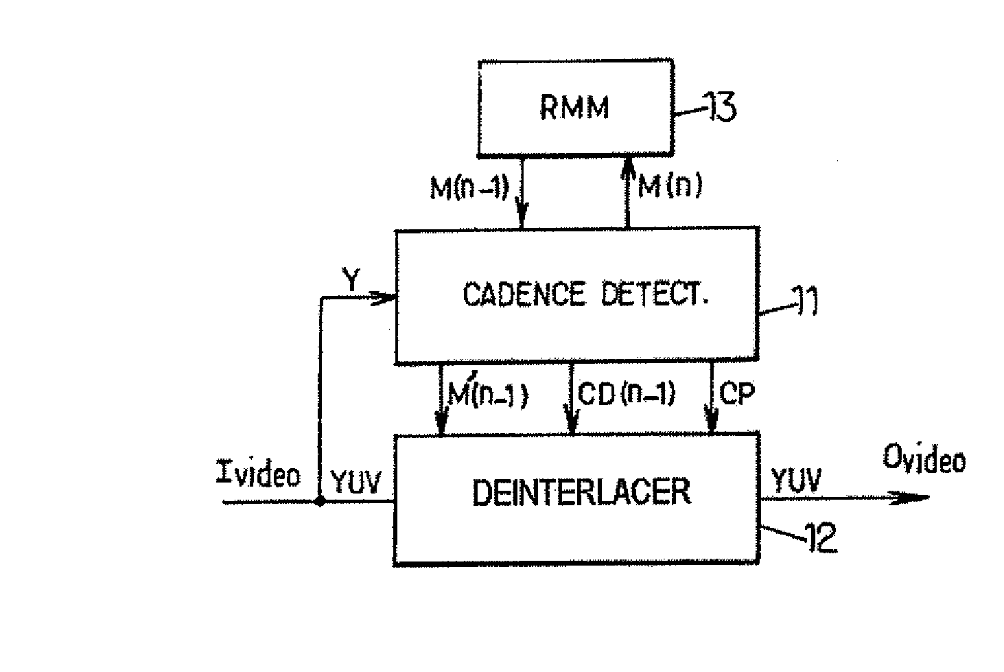
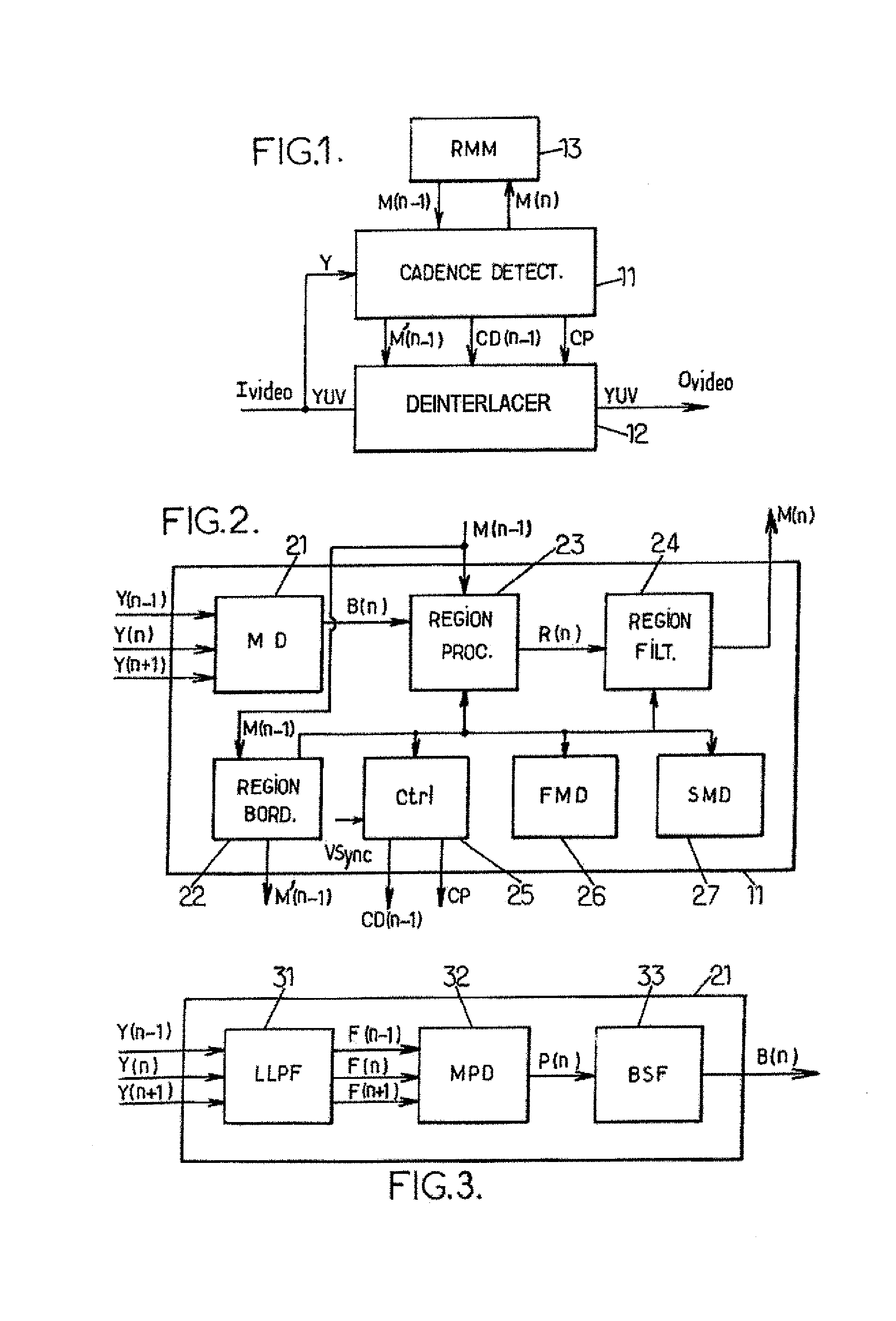
[0075]FIG. 1 schematically shows a processing system for processing a sequence of images, here a deinterlacing system, according to one embodiment of the invention. In the embodiment illustrated, a cadence detector 11 is coupled with a deinterlacing device 12. Of course, the cadence detector of the invention may be used in other applications. For example, the cadence detector may be connected to a compression device to allow detection of redundant fields and therefore contribute to an efficient compression.

[0076] In the embodiment illustrated, only the luminance pixels (luma pixels) Y of a video input lvideo are used by the cadence detector 11. Alternatively, a more complex and more reliable motion detection could be implemented on the basis of comparisons of chrominance pixels (chroma pixels).

[0077] A region map memory 13 or RMM is provided for storing a previous segmentation into regions. The fields are subdivided ...


PUM


Abstract

In a method for detecting the cadence of a sequence of images, each pixel in each current field in the sequence of images is compared to at least one pixel in at least one previous field. A pixel motion phase value is assigned to each pixel in the field as a function of the result of that comparison. For each block of pixels in the current field, a block motion phase value is determined from the motion phase values of the pixels in the block. The current field is segmented into at least one region, with each region comprising a whole number of blocks, as a function of at least the determined block motion phase values. A region motion phase value is assigned to each region, based on the block motion phase values for the blocks in the region.

Description

PRIORITY CLAIM [0001] The present application is a translation of and claims priority from French Patent Application No. 06 05027 of the same title filed Jun. 6, 2006, the disclosure of which is hereby incorporated by reference to the maximum extent allowable by law. BACKGROUND OF THE INVENTION [0002] 1. Technical Field of the Invention [0003] The present invention relates to detecting the cadence of a sequence of images. [0004] 2. Description of Related Art [0005] The detection of the cadence of a sequence of images is based on a search for a cadence pattern, for example “10010”, in a sequence of bits representative of the motion between one field and another. Cadence is therefore understood to mean a successive repetition of at least one cadence pattern. [0006] Cadence detection may lead to determining the source format of an image sequence, or detecting the absence of motion (still pictures). Several source formats exist. For example, a video camera may capture 50 or 60 frames pe...

Claims


Application Information

Patent Timeline
IPC IPC(8): H04N11/20
CPCH04N5/144H04N7/012H04N7/0115
Inventor EYMARD, FRANKIEBARNICHON, CHRISTOPHE
Owner STMICROELECTRONICS SRL
Why Eureka
Try Eureka