Interferometric Measuring System

Inactive Publication Date: 2007-12-20
ROBERT BOSCH GMBH
View PDF8 Cites 2 Cited by
  • Summary
  • Abstract
  • Description
  • Claims
  • Application Information

AI Technical Summary

Benefits of technology

[0004] The object of the present invention is to provide an interferometric measuring system of the t

Problems solved by technology

Altogether, an interferometric measuring system

Method used


Image

  • Interferometric Measuring System
  • Interferometric Measuring System

Examples


Example

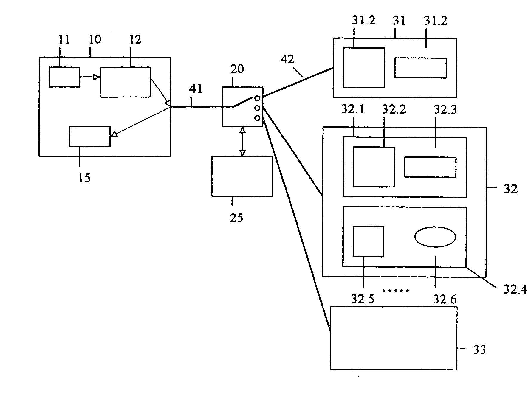
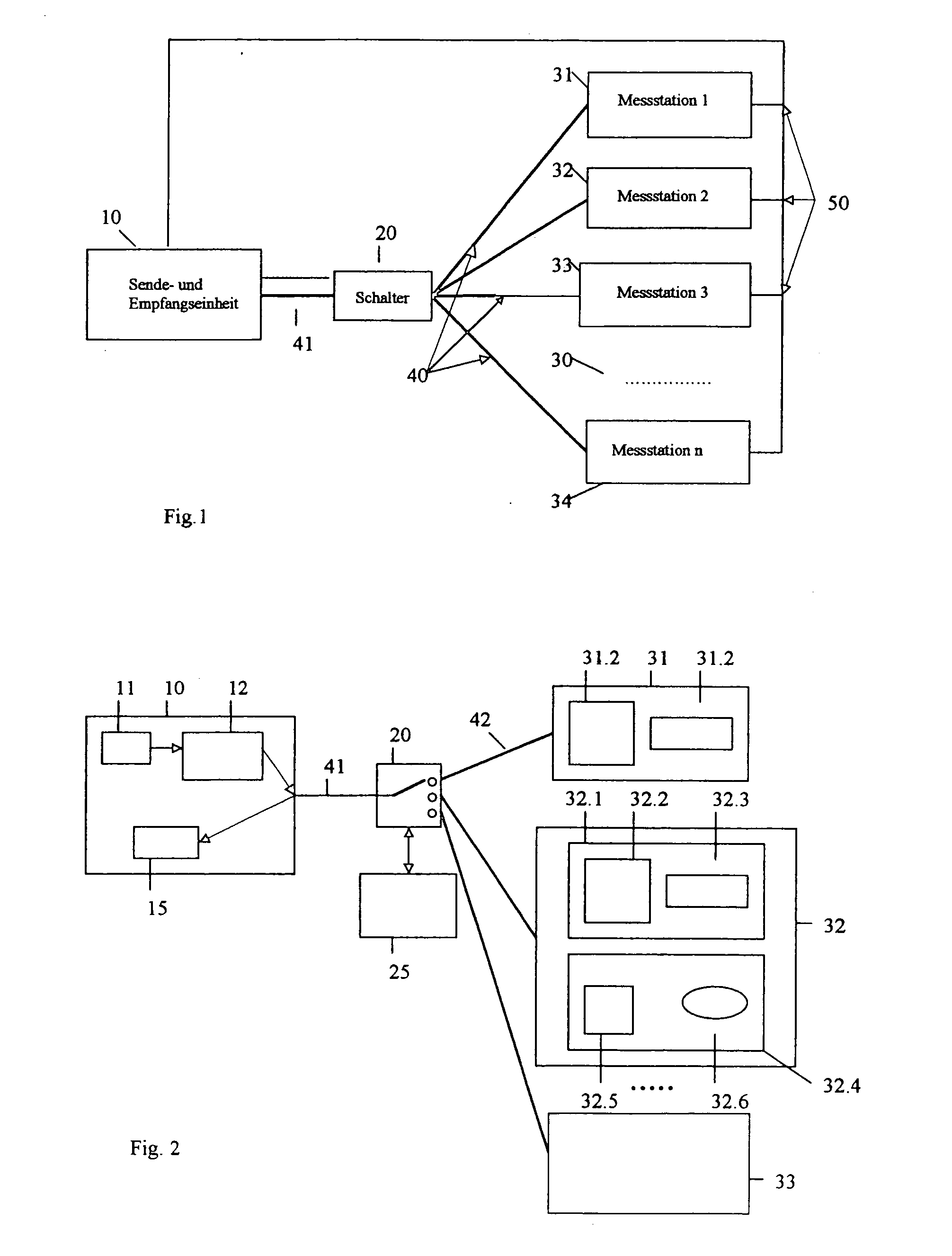
[0013]FIG. 1 shows an interferometric measuring system for measuring surface properties of an object, such as roughness, roundness, or also vibrations, the measuring system including a transmitter / receiver unit 10 and, connected thereto, a plurality of measuring stations 31, 32, 33, 34 of a measuring system 30 which are optically connected to transmitter / receiver unit 10 via a common optical path 40, a switching device 20 connected thereto, and optical paths 42 leading to the respective measuring stations 31, 32, 33, 34. Moreover, transmitter / receiver unit 10 and measuring stations 31, 32, 33, 34 are interconnected via respective electrical connections. Common optical path 40 and optical paths 42 leading to the respective measuring stations 31, 32, 33, 34 are advantageously formed by optical fibers 41 and 42, which are, in particular, monomode optical fibers.

[0014] As shown in FIG. 2, transmitter / receiver unit 10 accommodates components of the transmitting element, namely a radiati...


PUM


Abstract

The present invention relates to an interferometric measuring system for measuring, for example, shape deviation, position, surface properties, vibrations, of an object, the measuring system including a transmitting element having a modulation interferometer and a radiation source for short-coherent radiation, as well as a measuring probe system connected thereto for supplying the radiation via a common optical path, and further including a receiving element for analyzing the measuring radiation returning from the measuring probe system, said receiving element being combined with the transmitting element in a transmitter/receiver unit. A reduction in complexity and cost combined with enhanced application possibilities is achieved in that the measuring probe system includes a plurality of measuring probes coupled to the common optical path via respective optical paths, and in that a switching device is disposed at a coupling point between the common optical path and the respective optical paths to the measuring probes, said switching device allowing the different measuring probes to be individually brought into a bidirectionally transmitting connection with the transmitter/receiver unit for the radiation supplied by the modulation interferometer, on the one hand, and the measuring radiation, on the other hand.

Description

FIELD OF THE INVENTION [0001] The present invention relates to an interferometric measuring system for measuring, for example, shape deviation, position, surface properties, vibrations, of an object, the measuring system including a transmitting element having a modulation interferometer and a radiation source for short-coherent radiation, as well as a measuring probe system connected thereto for supplying the radiation via a common optical path, and further including a receiving element for analyzing the measuring radiation returning from the measuring probe system, said receiving element being combined with the transmitting element in a transmitter / receiver unit. BACKGROUND INFORMATION [0002] An interferometric measuring system of this type is described in German Published Patent Application No. 198 08 273. This known interferometric measuring system combines the methods of the heterodyne technique and dual-wavelength interferometry, which are known per se, using short-coherent ra...

Claims


Application Information

Patent Timeline
IPC IPC(8): G01B9/02G01B11/16G01B11/30G01D5/353
CPCG01B11/2441G01D5/35383G01B9/02065G01B9/02027G01B9/0209G01B9/02007
Inventor DRABAREK, PAWEL
Owner ROBERT BOSCH GMBH
Why Eureka
Try Eureka