

Infrared clinical thermometer
a thermometer and infrared technology, applied in the field of thermometers, can solve the problems of inconvenience for users, inconvenient use of infrared ear thermometers, etc., and achieve the effect of fast obtaining forehead temperature or ear temperatur
- Summary
- Abstract
- Description
- Claims
- Application Information
AI Technical Summary
Benefits of technology
Problems solved by technology
Method used
Image

Examples
first embodiment
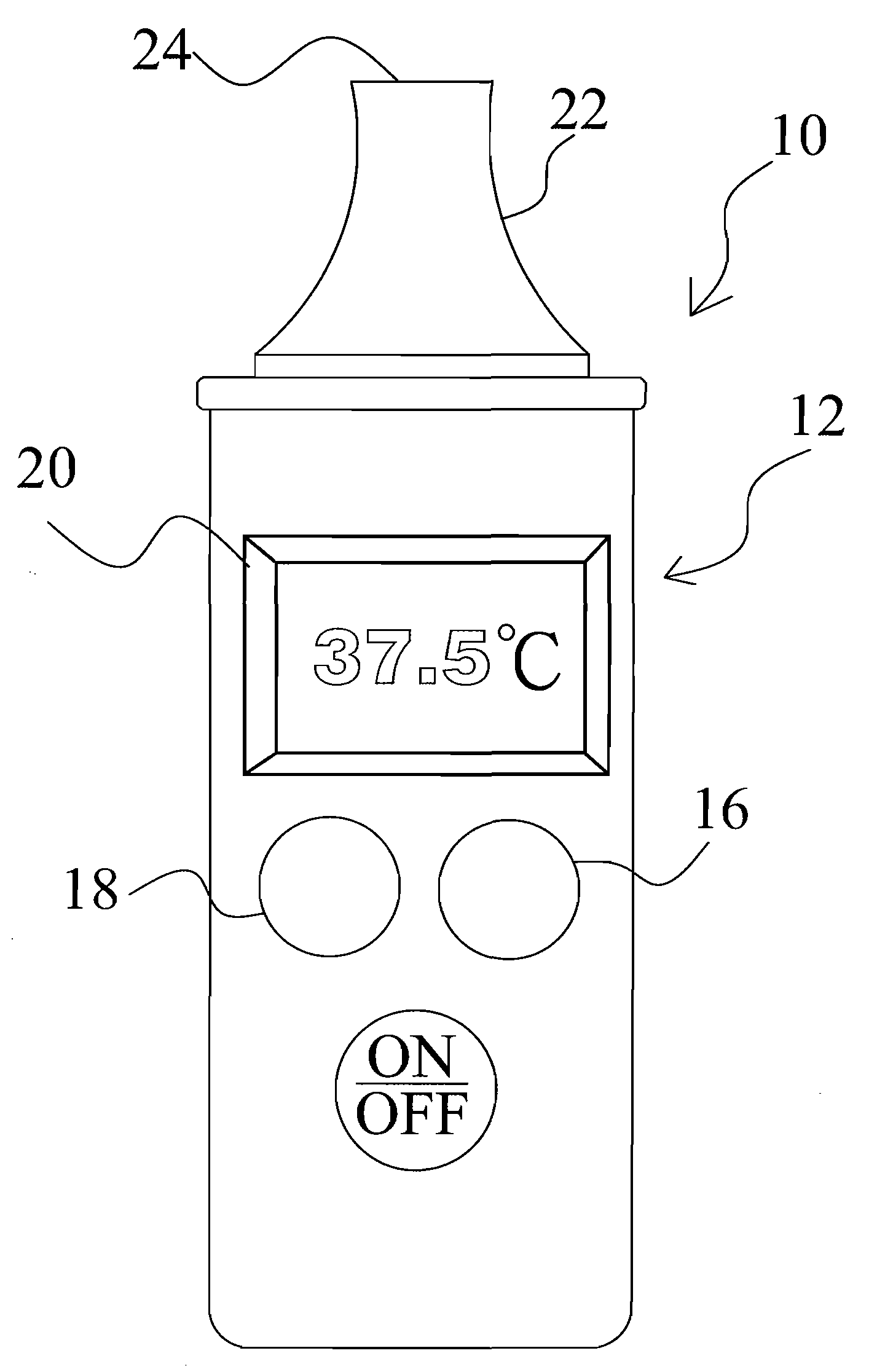
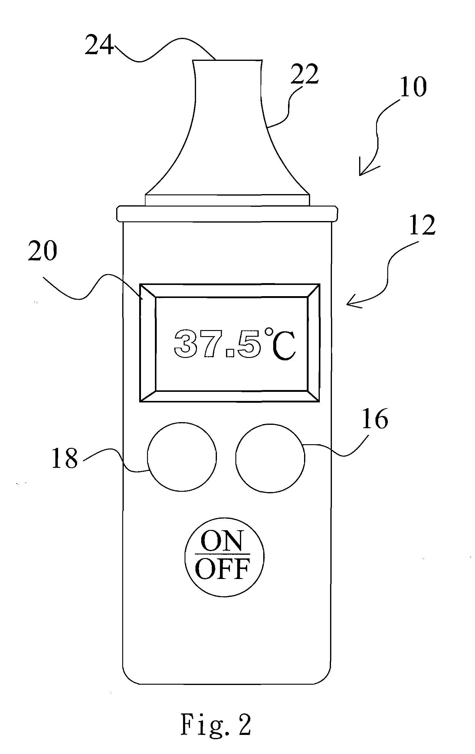
[0023]Refer to FIG. 2 and FIG. 3 respectively a diagram schematically showing the present invention and a block diagram showing the circuit of the infrared clinical thermometer according to the present invention. According to this embodiment, the infrared ear thermometer 10 comprises a thermometer body 12 having a circuit board thereinside (not shown in the drawings); a microprocessor 14 arranged on the circuit board; an ear temperature button 16 and a forehead temperature button 18 arranged on the thermometer body 12 and coupled to the microprocessor 14; a display unit 20 arranged on the thermometer body 12 and coupled to the microprocessor 14; and a temperature sensing unit 22 arranged at one end of the thermometer body 12 wherein the temperature sensing unit 22 comprises an infrared sensor 25 therein and the infrared sensor 25, for detecting infrared radiation from the ear or forehead, is coupled to the microprocessor 14. Further, the temperature sensing unit 22 has a window 24 t...
second embodiment
[0025]Refer to FIG. 4 a diagram schematically showing the present invention. According to this embodiment, the infrared ear thermometer 30 comprises a thermometer body 32 having a circuit board (not shown in the drawings); a microprocessor (not shown) arranged on the circuit board for controlling the activities of the infrared ear thermometer 30; a display unit 34 arranged on the thermometer body 32 and coupled to the microprocessor; an ear temperature button 36 and a forehead temperature button 38 arranged on the thermometer body 32 and coupled to the microprocessor; and a temperature sensing unit 42 arranged at one end of the thermometer body 32 and having an infrared sensor (not shown), coupled to the microprocessor, therein for detecting infrared radiation from the ear or forehead, and having a window 40 that is transparent to infrared radiation. The operation of the infrared ear thermometer 30 is similar to that of the infrared ear thermometer 10 and will not repeat herein.
[002...
third embodiment
[0027]Refer to FIG. 6A and FIG. 6B diagrams schematically showing the present invention. According to this embodiment, the infrared ear thermometer 50 comprises a thermometer body 52 having a circuit board (not shown in the drawings); a microprocessor (not shown) arranged on the circuit board for controlling the activities of the infrared ear thermometer 50; a display unit 54 arranged on the thermometer body 52 and coupled to the microprocessor; an ear temperature button 66 and a forehead temperature button 68 arranged on the thermometer body 52 and coupled to the microprocessor; a temperature sensing unit 58 arranged at one end of the thermometer body 52 and having an infrared sensor, coupled to the microprocessor, therein for detecting infrared radiation from the ear or forehead, and having a window 56 that is transparent to the infrared radiation; a slide rail arranged on the thermometer body 52 and having a first blocker 63 and a second blocker 64 respectively arranged at two en...
PUM
 Abstract
Description
Claims
Application Information