
Method for determining the distance of visibility for a driver of a vehicle

Inactive Publication Date: 2007-12-20
VALEO VISION SA
View PDF10 Cites 12 Cited by
  • Summary
  • Abstract
  • Description
  • Claims
  • Application Information

AI Technical Summary

Benefits of technology

[0023]As will be seen below in detail, determination of the distance of visibility only utilizes simple linear combinations, this determination thus being faster than that of the prior art. Moreover, it removes uncertainties, related to the noise generated by calculation of the derivatives, from the prior art, since there is no longer any derivative calculation. Lastly this method can be used in the presence of obstacles on the road, without determination of the distance of visibility being disrupted
[0032]the second tangent is parallel to the first tangent. This renders the possibility of having simple and fast calculation.
[0035]the distance of visibility is determined on the basis of the sweep-line found and by means of a correspondence table or a trigonometric calculation. Determining the distance of visibility by reading a correspondence table is very fast.

Problems solved by technology

Firstly calculation of the derivative leads to problems in interpretation, significant inaccuracies and errors, particularly if there is an obstacle on the road over which a vehicle is travelling, for example another vehicle, a bridge and the like. Indeed such an obstacle will generate a plurality of points of inflection when calculating the derivative, hence the difficulty in distinguishing the various points of inflection if they are close to one another and in choosing the good inflection point corresponding to the distance of visibility searched.
Secondly the calculation of the derivative amplifies the noise generated on the luminosity curve causing uncertainties on the curve itself.
Lastly calculation of the derivative represents a heavy computational load.

Method used


Image

  • Method for determining the distance of visibility for a driver of a vehicle
  • Method for determining the distance of visibility for a driver of a vehicle
  • Method for determining the distance of visibility for a driver of a vehicle

Examples


Embodiment Construction

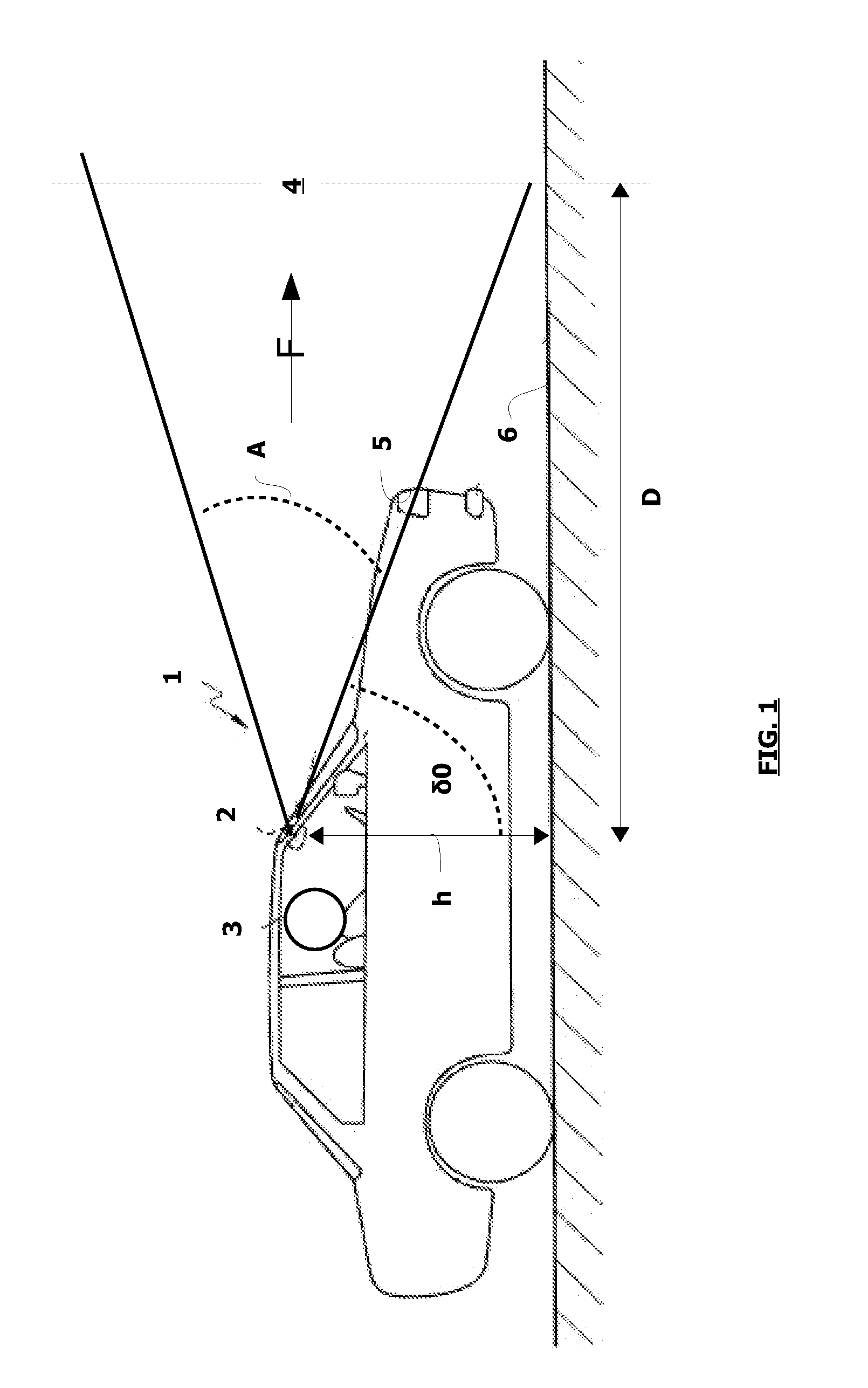
[0064]On FIG. 1 a vehicle 1 equipped with a camera 2 and driven by a driver 3, who can observe a scene in a field of space 4 located in front of the vehicle when his vehicle 1 is stationary or moving, is shown in a diagrammatic way.

[0065]Camera 2 is situated at a height h from the surface of road 6 and is located for example in the front of the vehicle or on the side. It is fitted for example behind the windscreen and points to the front of the scene in the traveling direction F of the vehicle. Thus camera 2 comprises a total angular field A which can be compared to the field of space located in front of vehicle 1, this total angular field A being defined by a minimum sight angle α0 illustrated on FIG. 1. A distance of visibility D for a driver will be linked to the position of camera 2 on vehicle 1.

[0066]In order to determine the distance of visibility D for driver 3 when there is an element BR disrupting or modifying the visibility, particularly if this disruptive element is fog, ...


PUM


Abstract

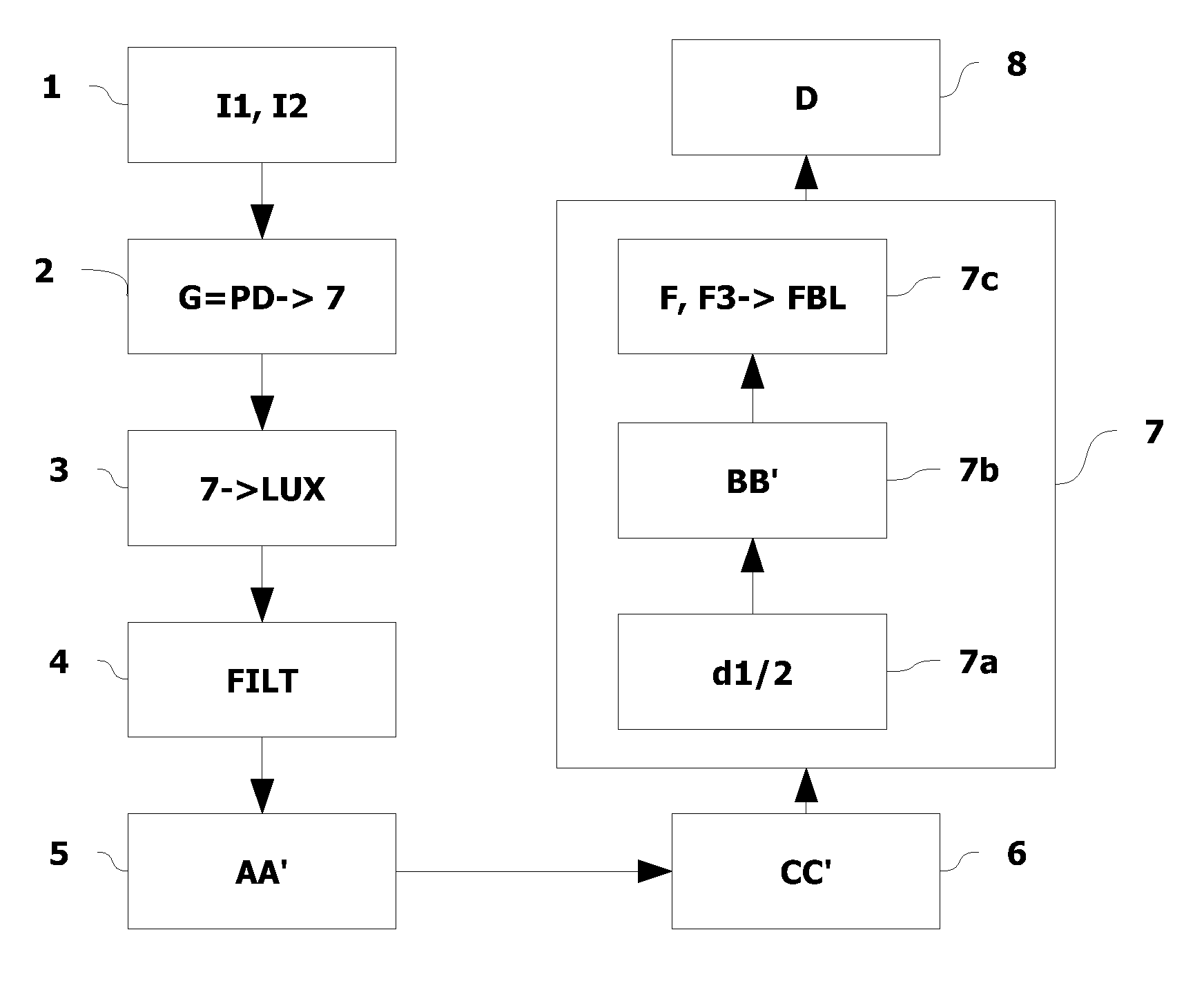
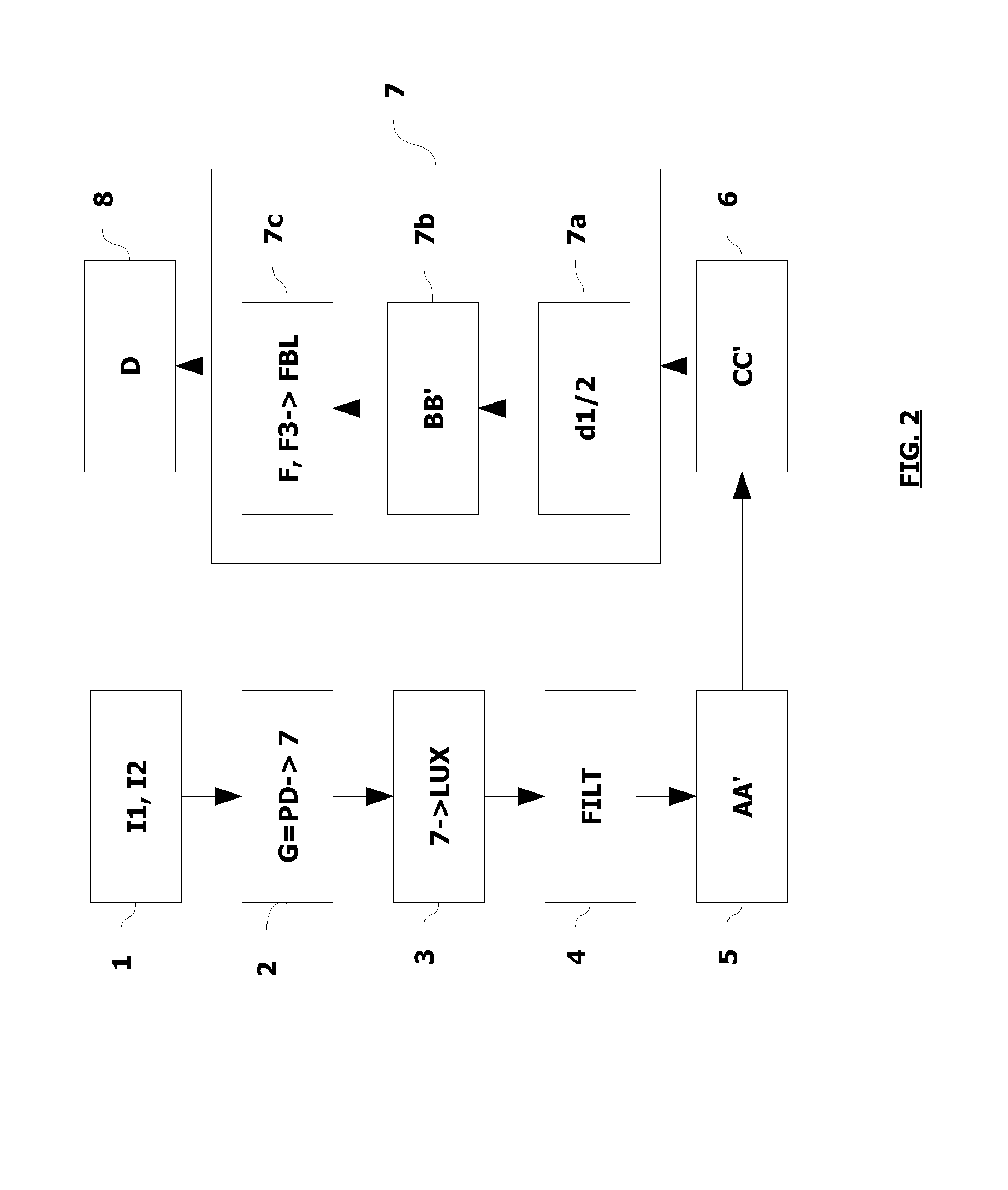
A method for determining the distance of visibility for a driver of a vehicle in the presence of an element disrupting the visibility of the driver, the method comprising the following steps: determining the luminosity of the pixels of a region of an image taken in the field of vision of the driver, resulting in a luminosity curve, determining a first tangent to the curve of luminosity, determining a second tangent to the curve of luminosity, determining a sweep-line according to the first tangent and second tangent, the sweep-line being representative of the distance of visibility.

Description

BACKGROUND OF THE INVENTION[0001]1. Field of the Invention[0002]The present invention relates to a method for determining a distance of visibility for a driver of a vehicle in the presence of an element disrupting the visibility of the driver. The disruptive element is for example fog and the vehicle, a motor vehicle for example.[0003]2. Description of the Related Art[0004]According to a known prior art EP 1 422 663 A1, such a method of determination comprises the following steps:[0005]videoing at least one image of a field of space located in front of the vehicle, the image being defined by an array of pixels,[0006]separating the image in two parts by a line passing through a pre-set point,[0007]determining the luminosity of the pixels of the line, resulting in a curve of luminosity,[0008]determining an inflection point of the luminosity curve by calculating the derivative of the curve,[0009]determining the distance of visibility of the driver of the vehicle according to the positi...

Claims


Application Information

Patent Timeline
IPC IPC(8): G06K9/00
CPCG01S11/12G06T7/606G06T7/004G06K9/00791G06T7/70G06T7/66G06V20/56
Inventor REBUT, JULIENLELEVE, JOEL
Owner VALEO VISION SA
Learn More