Screw

a screw and screw body technology, applied in the field of screws, can solve the problems of water seeping into the space, debris easily extruding to the surface of the object, and still some defects in the above conventional screws,

Inactive Publication Date: 2007-12-20
HSIEH JUI TSE +1
View PDF0 Cites 8 Cited by
  • Summary
  • Abstract
  • Description
  • Claims
  • Application Information

AI Technical Summary

Benefits of technology

[0010] It is an object of the present invention to provide a screw having an enlarged head with a plurality of ribs defined at the bottom surface thereof, thereby aiding the screw in being firmly screwed into the object and being impervious to water, so as to achieve the waterproof effect.
[0012] The screw in accordance with the present invention comprises an enlarged head, a shank with threads and a drilling portion, and a conical section. In Particular, the ratio of the outer diameter of the shank to the outer diameter of the head is 1:3.5˜5.5, whereby the screw has a broad area to cover the debris of the object for keeping a clean appearance. Additionally, the enlarged head has a bottom surface with a plurality of ribs arranged thereon, thereby providing with a good resistance of extraction and the waterproof effect after screwing.

Problems solved by technology

However, there are still some defects with regard to the above conventional screws:
Generally, the screw 1 comprises the head having a larger diameter than that of the shank, and the ratio of the outer diameter of the shank to the outer diameter of the head is normally arranged as 1:2, which reveals that the head has relatively less area to make the debris of the object covered and squeezed beneath the head, which results in the debris easily extruded to the surface of the object and in an untidy appearance after screwing.
Due to the ejected debris, the bottom surface of the head is unable to fully contact with the surface of the object, which easily causes the water seeped into the space between the bottom surface and the surface of the object while screwing.
Accordingly, the ribs may be disposed on the bottom surface to overcome the above problem; however, the ribs formed in a helical state as shown in FIG. 3 may preferably increase the screwing torque, instead of ensuring a good contact with the surface of the object, therefore the screw 2 may not effectively block the infiltration of the water.

Method used


Image

  • Screw
  • Screw
  • Screw

Examples


Embodiment Construction

[0022] Before the present invention is described in greater detail, it should be noted that the similar elements are denoted by the same reference numerals throughout the disclosure.

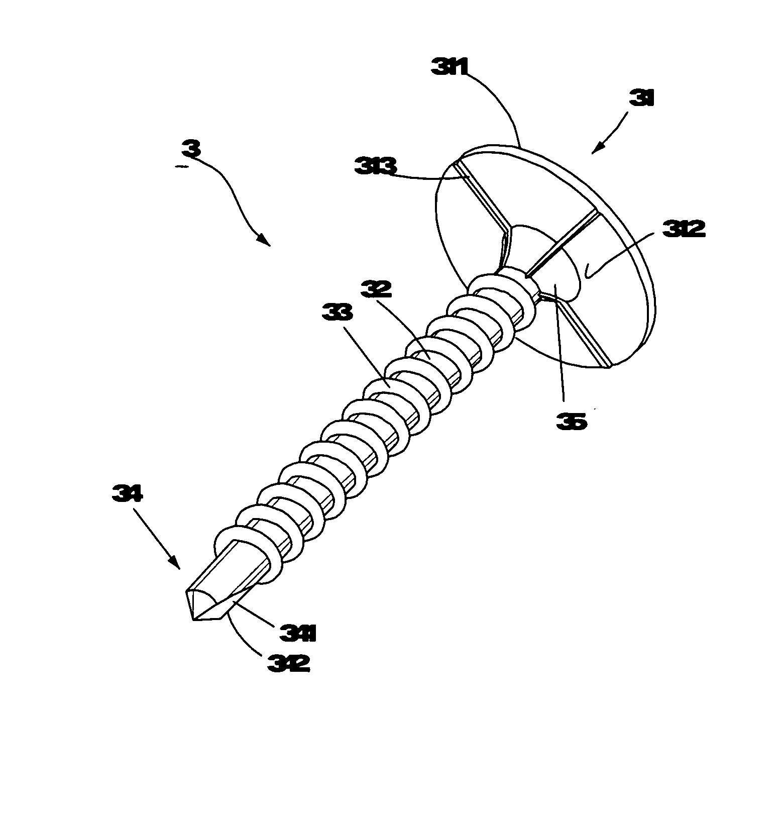
[0023] Referring to FIG. 4, the screw 3 of the first preferred embodiment comprises an enlarged head 31, a shank 32 longitudinally extended from the head 31, and a conical section 35 extended from the head 31 in contact with the shank 32; wherein, the enlarged head 31 comprises an upper surface 311 and a bottom surface 312 defined opposite thereto; the bottom surface 312 has a plurality of rids 313, which are extended from the outer periphery of the bottom surface 312, across the conical section 35 and terminated in contact with the shank 32; the ratio of the outer diameter of the shank 32 to the outer diameter of the head 31 is 1:3.5˜5.5, and the ratio 1:3.5 is adopted in this preferred embodiment. Additionally, the shank 32 has a plurality of threads 33 disposed thereon and a drilling portion 34 forme...


PUM


Abstract

The present invention pertains to a screw comprising an enlarged head and a shank with threads. In particular, the enlarged head has a bottom surface comprising a plurality of ribs extended from the outer periphery thereof to the shank, thereby providing with a good resistance of extraction and a good waterproof effect. Additionally, due to the ratio of the outer diameter of the shank to the outer diameter of the head being 1:3.5˜5.5, the debris extruded out of the object hence can be covered and squeezed beneath the enlarged head, so as to maintain a clean appearance.

Description

CROSS-REFERENCE TO RELATED APPLICATION [0001] This application is a continuation-in-part of the U.S. patent application Ser. No. 11 / 405,409 filed on Apr. 18, 2006.BACKGROUND OF THE INVENTION [0002] 1. Field of the Invention [0003] The present invention relates to a screw, in particular a screw having an enlarged head which comprises a bottom surface with a plurality of ribs arranged thereon, thus ensuring a good resistance of extraction, simultaneously providing with the waterproof effect and maintaining a clean appearance. [0004] 2. Description of the Related Art [0005] Referring to FIG. 1, a conventional screw 1 of the U.S. Application No. 2005 / 0226701 comprises a head 11, a shank 12 with a plurality of threads 13 disposed thereon, and a knurling portion 14 disposed between the head 11 and the threads 13; wherein, the head 11 comprises a bottom surface 111 defined at the underside thereof and a neck portion 112 extended from the bottom surface 111 to the shank 12; the head 11 havi...

Claims


Application Information

Patent Timeline
Patent Type & Authority Applications(United States)
IPC IPC(8): F16B25/10
CPCF16B25/103F16B35/06F16B33/008
Inventor HSIEH, JUI-TSEWANG, CHIU-YUEH
Owner HSIEH JUI TSE
Why Eureka
Try Eureka