Coaxial cable

a coaxial cable and cable technology, applied in the field of cables, can solve the problems of low yield and high cost of conventional coaxial cables, and achieve the effect of high shielding efficiency and suitable for low-cost mass production

Active Publication Date: 2007-12-20
BEIJING FUNATE INNOVATION TECH +1
View PDF7 Cites 79 Cited by
  • Summary
  • Abstract
  • Description
  • Claims
  • Application Information

AI Technical Summary

Benefits of technology

[0009]Accordingly, a coaxial cable that has great shield effectiveness and is suitable for low-cost mass production is provided in the present cable. The coaxial cable includes at least one conducting wire; at least one insulting layer, each insulating la

Problems solved by technology

However, the conventional coaxial ca

Method used


Image

  • Coaxial cable
  • Coaxial cable
  • Coaxial cable

Examples


Embodiment Construction

[0018]The present coaxial cable is further described below with reference to the drawings.

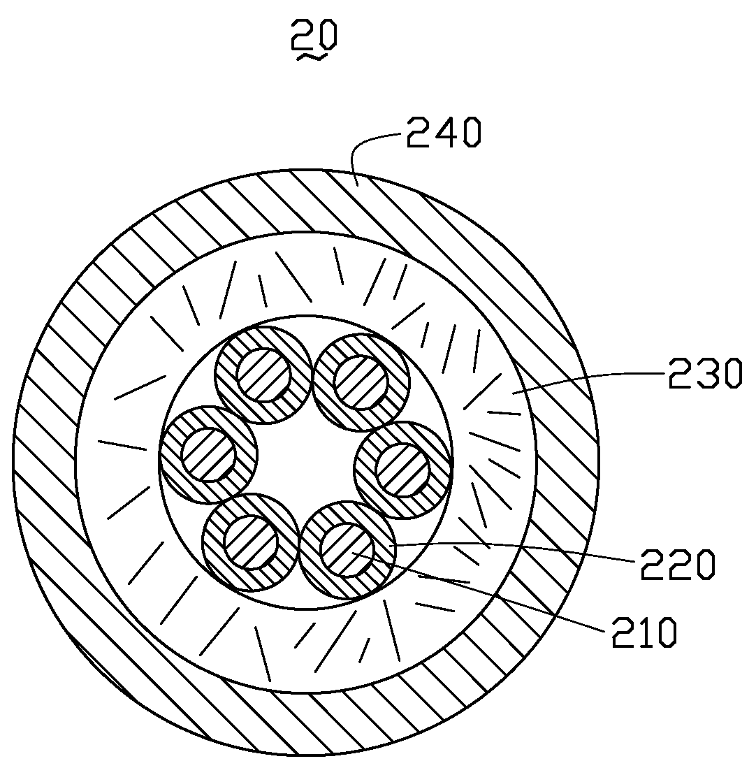
[0019]The present coaxial cable includes at least one conducting wire, at least one insulating layer, each insulating layer respectively surrounding a corresponding conducting wire, at least one shielding layer encompassing the at least one insulating layer, and a sheath wrapping the above-mentioned three parts thereof. The coaxial cable is, usefully, an electromagnetic interference (EMI) shield cable.

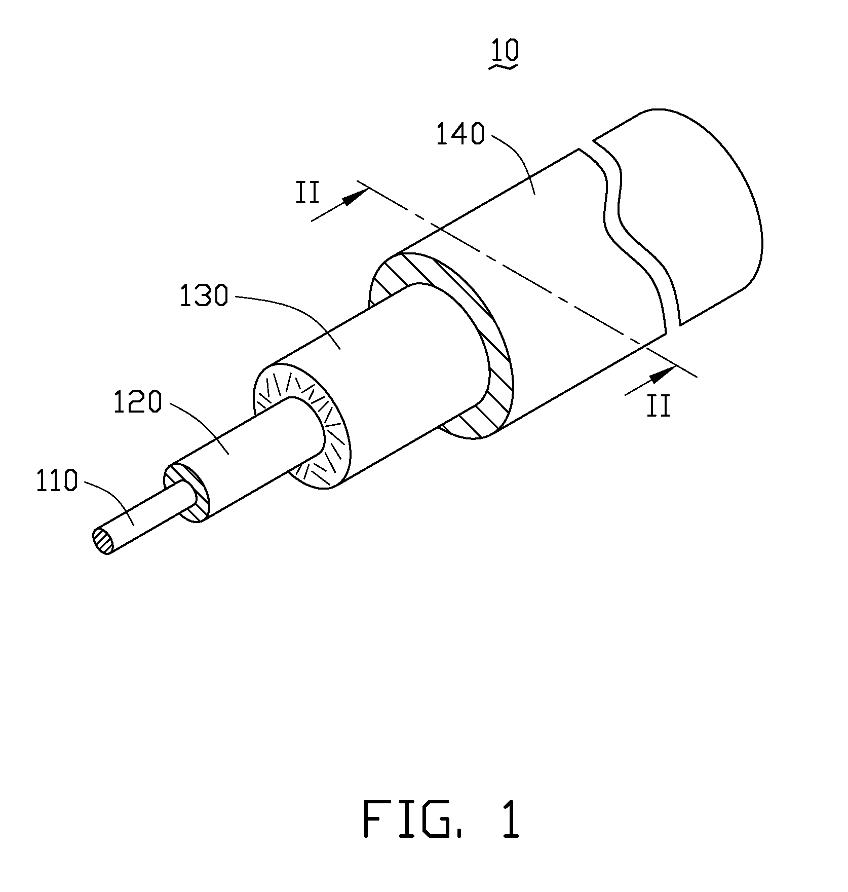
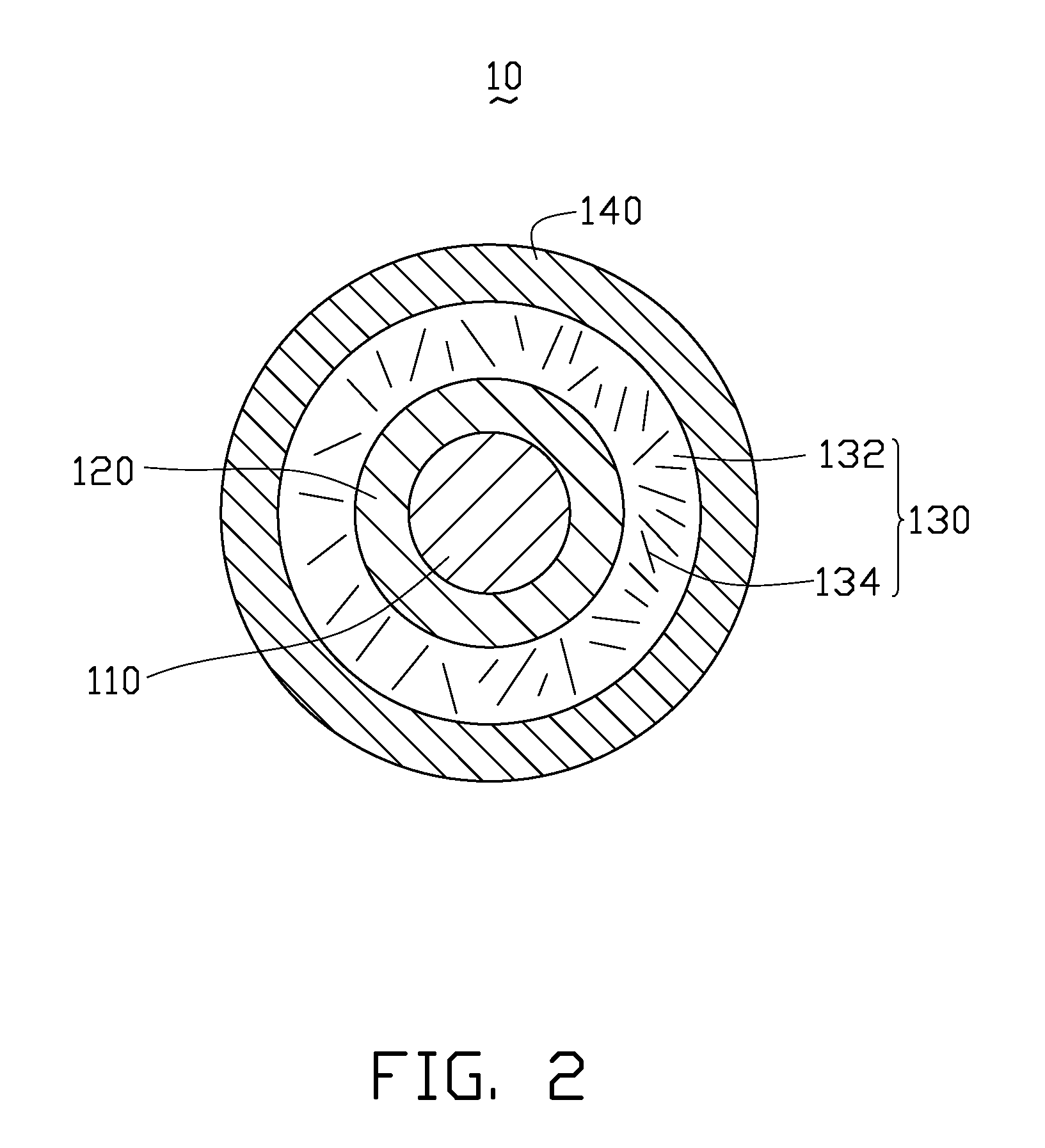
[0020]Referring to FIG. 1, a coaxial cable 10, according to the first embodiment, is shown. The coaxial cable 10 includes a conducting wire 110, an insulating layer 120, a shielding layer 130 and a sheath 140. The axis of the conducting wire 110, the insulating layer 120, the shielding layer 130, and the sheath 140 is consistent (i.e., such elements are coaxial), and the arrangement thereof is, in turn, from center to outer.

[0021]The conducting wire 110 can be a single wire or a number of stranded...


PUM


Abstract

A coaxial cable (10) includes at least one conducting wire (110), at least one insulting layer (120) coating a respective conducting wire, at least one shielding layer (130) surrounding the at least one insulting layer, and a single sheath (140) wrapping the at least one shielding layer. The shielding layer includes a polymer material (134) and a plurality of carbon nanotubes (132) embedded in the polymer material. The coaxial cable is, advantageously, an electromagnetic interference (EMI) shield cable.

Description

RELATED APPLICATIONS[0001]This application is related to commonly-assigned, co-pending application: entitled, “COMPOSITE CONDUCTOR AND ELECTRICAL CABLE USING THE SAME”, filed Nov. 24, 2006 (application Ser. No. 11 / 559,840). The disclosure of the above-identified application is incorporated herein by reference.BACKGROUND[0002]1. Field of the Invention[0003]The present invention relates to cables and, more particularly, to a coaxial cable.[0004]2. Discussion of Related Art[0005]A coaxial cable is an electrical cable including an inner conductor, an insulating layer, and a conducting layer, usually surrounded by a sheath. The inner conductor can be, e.g., a solid or braided wire, and the conducting layer can, for example, be a wound foil, a woven tape, or a braid. The coaxial cable requires an internal structure of an insulating layer (i.e., a dielectric) to maintain a physical support and a constant spacing between the inner conductor and the conducting layer, in addition to electrica...

Claims


Application Information

Patent Timeline
IPC IPC(8): H01R9/05
CPCH01B11/1808H01B11/1066
Inventor LIU, LIANGJIANG, KAI-LIFAN, SHOU-SHANCHEN, CEASARLEE, HSI-FUCHEN, GA-LANE
Owner BEIJING FUNATE INNOVATION TECH
Why Eureka
Try Eureka