
Method for Operating an Injection Molding Machine

a technology of injection molding machine and operating method, which is applied in the direction of auxillary shaping apparatus, manufacturing tools, ceramic shaping apparatus, etc., can solve the problems of increasing hardware costs and high hardware costs, and achieve the effect of exceeding the transition criterion at the output of regulating or controlling means

Inactive Publication Date: 2007-12-27
SIEMENS AG
View PDF1 Cites 14 Cited by
  • Summary
  • Abstract
  • Description
  • Claims
  • Application Information

AI Technical Summary

Benefits of technology

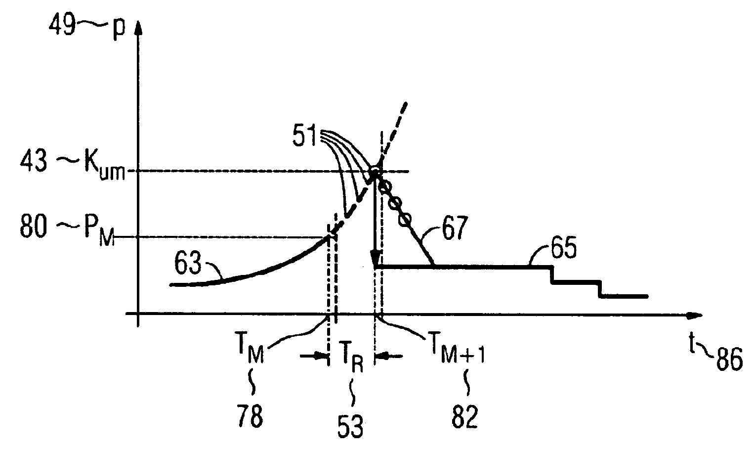
[0015] Using an extrapolation value makes it possible to, for example, avoid the occurrence of spikes, adversely affecting the quality of an injection-molded part, at an output of the regulating or controlling means. Exceeding of the transition criterion at the output of the regulating or controlling means can also be prevented. The regulating or, as the case may be, controlling means therein relates also to an associated device. The transition criterion relates to, for example, a pressure or a path.
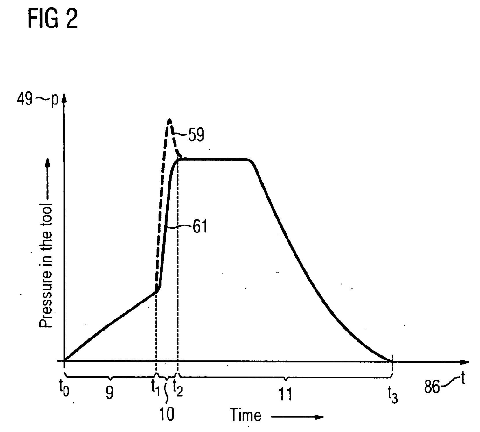
[0017] That problem is inventively resolved using the extrapolation value. By means of the method according to the invention the pressure curve is extrapolated during the injection phase before the switchover instant is reached. The pressure curve relates to, for example, the pressure in the molding tool, in an injection nozzle, and / or in the space in front of the screw. The method according to the invention makes a consistent pressure curve possible and avoids pressure spikes adversely affecting the item requiring to be injection-molded in the molding tool.

Problems solved by technology

Sampling times in the range of 100 μs are very hardware intensive.
Aside from the pure computing power, all the actuators and sensors involved also have to support said times, which increases the hardware costs.
On the other hand, methods having an interrupt reaction preclude using a cycle-synchronous periphery because resynchronizing is not possible here.

Method used


Image

  • Method for Operating an Injection Molding Machine
  • Method for Operating an Injection Molding Machine
  • Method for Operating an Injection Molding Machine

Examples


Embodiment Construction

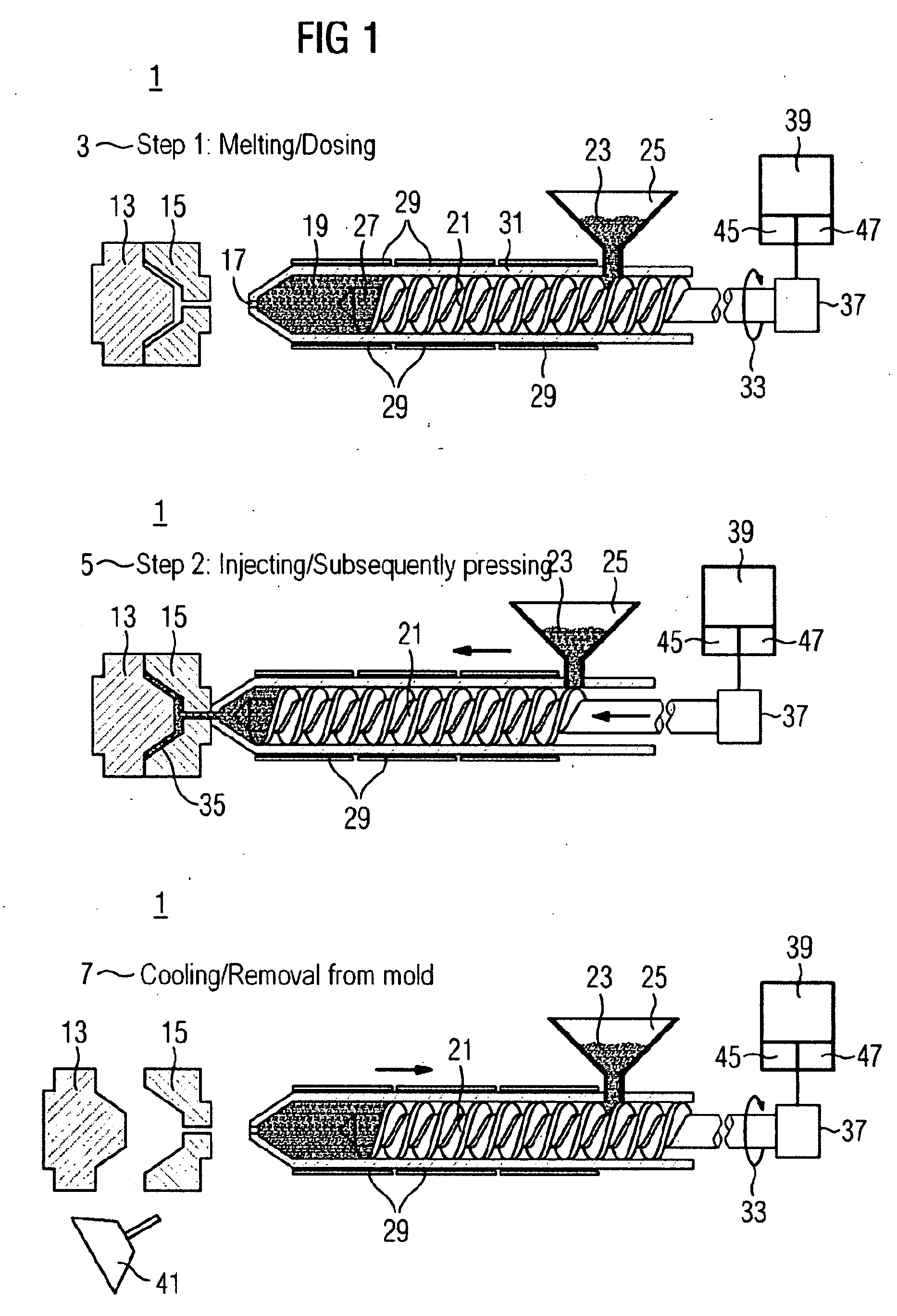
[0050] The representation in FIG. 1 shows three steps 3, 5, 7 of a molding process. The first step 3 relates to melting and dosing, the second step 5 relates to injecting and subsequent pressing, and the third step 7 relates to cooling and removal from the mold. The molding process relates to an injection molding machine 1. The injection molding machine 1 has a screw 21. The screw 21 is located in a screw cylinder 31. The injection molding machine 1 furthermore has a funnel 25. The funnel 25 can be charged with plastic pellets 23. The plastic pellets 23 can be transported into a space 19 in front of the screw through a rotational movement 33 of the screw 21. Through friction or, as the case may be, by means of an electric heating means 29, the plastic pellets are heated during transportation to form a molten mass. Through a rotational movement 33, the molten mass accumulates in a space 19 in front of the screw. The rotational movement 33 can be achieved by means of, for example, an ...


PUM

PropertyMeasurementUnit
timeaaaaaaaaaa
pressureaaaaaaaaaa
rotational movementaaaaaaaaaa

Abstract

There is described a method for operating an injection molding machine, which comprises a forming tool, an injecting device and a digital regulating and / or control device at least for regulating and / or controlling the injecting device. When regulating and / or controlling the injecting device, a pressure regulation and / or pressure control for regulating and / or controlling the injection device is switched over subject to the reaching of a transition criterion, whereby a value is established that is used for determining the transition criterion. At least one extrapolation value is established for at least one measured value, whereupon the extrapolation value is compared with the transition criterion and the pressure regulation and / or control of the injection molding machine or is switched over to the pressure regulation and / or the pressure control.

Description

CROSS REFERENCE TO RELATED APPLICATIONS [0001] This application is the US National Stage of International Application No. PCT / EP2005 / 055146, filed Oct. 11, 2005 and claims the benefit thereof. The International Application claims the benefits of German application No. 10 2004 051 109.8 DE filed Oct. 19, 2004, both of the applications are incorporated by reference herein in their entirety.FIELD OF INVENTION [0002] The invention relates to a method for operating an injection molding machine or, as the case may be, to an injection molding machine for implementing said method. BACKGROUND OF INVENTION [0003] Methods of said type are known from, for instance, the book titled “Handbuch Spritzgieβen” [meaning: Injection Molding Handbook] by Friedrich Johannaber and Walter Michaeli, published by Carl Hanser Verlag in 2001 (ISDN 3-446-15632-1). A process sequence for injection molding is described in, for example, chapter 5.2 (pages 300 to 337). Examples of various models of injection molding...

Claims


Application Information

Patent Timeline
Patent Type & Authority Applications(United States)
IPC IPC(8): B29C45/77
CPCB29C45/77B29C2045/776B29C2945/76083B29C2945/76187B29C2945/76989B29C2945/76595B29C2945/76735B29C2945/76785B29C2945/76498
Inventor HOFMANN, WERNERKRAM, RAIMUNDOBERNDORFER, KLAUS
Owner SIEMENS AG
Learn More