Method & Apparatus For Magnetically Coupling Incremental Weights To Exercise Apparatus

a technology of incremental weights and magnetic coupling, which is applied in the field of exercise equipment, can solve the problems of affecting the safety and efficacy of exercise equipment, affecting the safety of exercise equipment, and not being usable with non-metallic weight plates,

Active Publication Date: 2007-12-27
ACE SPECIALTY +1
View PDF27 Cites 30 Cited by
  • Summary
  • Abstract
  • Description
  • Claims
  • Application Information

AI Technical Summary

Problems solved by technology

First, they have not been usable with non-metallic weight plates, although many dumbbells and bar bells utilize plastic weight plates or plates made of other non-magnetic material.
Accordingly, the inability, to use magnetically coupled incremental weight plates with increasingly popular non-magnetic dumbbell and barbell weight plates is a severe limitation.
Secondly, there has been a need for strong magnetic attraction between the incremental weight plate and the dumbbell / barbell weight plate to which it is attached.
In addition to safety concerns that arise whenever a weight plate can fall from an exercise device, it is undesirable for the incremental weight to shift position during an exercise movement because the resulting imbalance can detract from the safety and efficacy of the exercise movement.
The strong magnetic attraction thus required not only makes it difficult to remove the incremental weight plate from the exercise device, but can also scratch or mar the weight plate surface to which the incremental weight attaches.
In addition to adversely effecting the aesthetics of the device, the scratching of the plating material on a weight plate.
Moreover, the magnetic micro weights are coupled to coated weight plates on some weight plate devices, and the decoupling effort can scratch or mar the coating, leading to the rusting of the underlying surface.

Method used


Image

  • Method & Apparatus For Magnetically Coupling Incremental Weights To Exercise Apparatus
  • Method & Apparatus For Magnetically Coupling Incremental Weights To Exercise Apparatus
  • Method & Apparatus For Magnetically Coupling Incremental Weights To Exercise Apparatus

Examples


second embodiment

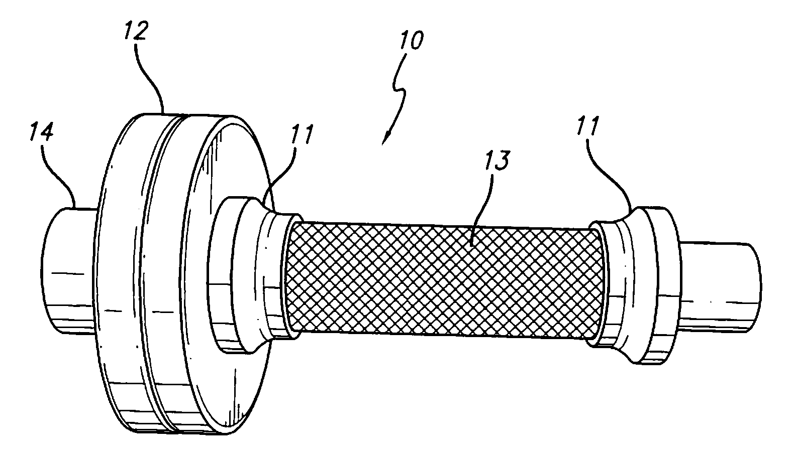
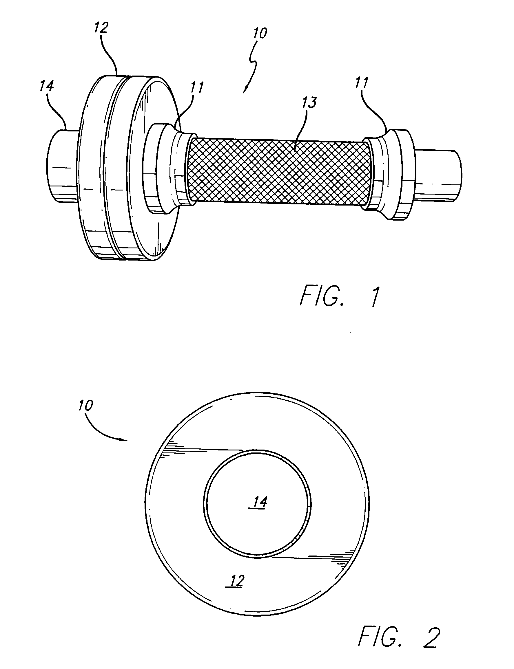
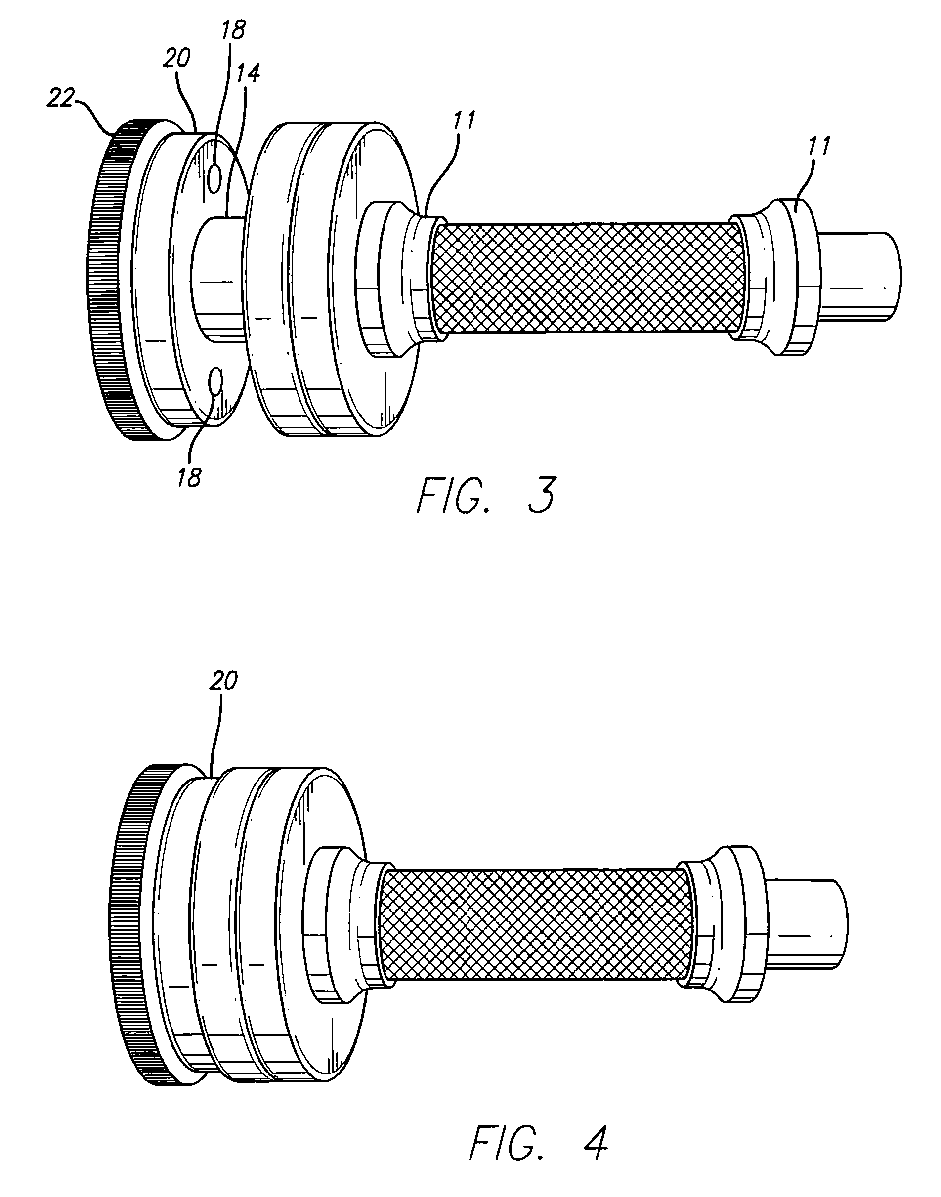
[0034]the invention is shown in FIGS. 8-11. FIG. 8 is a front elevation view of a dumbbell of the “adjustable” type, wherein weight plates are secured on the bar by removable collars that permit the user to add or remove individual weight plates to the dumbbell. FIG. 9 is a left side elevation view of the dumbbell of FIG. 8, and FIG. 10 is a front elevation view of the dumbbell of FIG. 8, showing the incremental weight plate 34 positioned for mounting onto the dumbbell in accordance with the invention.

[0035]In this embodiment, outer weight plates 32 and incremental weight plates 34 are mounted on opposite ends of a shaft 35 that extends through the dumbbell handle 37. As will become clear, the outer weight plates 32 need not be magnetically responsive but can, instead, be made of polyurethane or other commonly utilized plastic material such as that found in less expensive dumbbell sets.

[0036]FIG. 11 is a left side elevation view of the right incremental weight plate 34 of FIG. 8, sh...

third embodiment

[0040]FIG. 12 illustrates the invention. FIG. 12 is a front elevation view of a dumbbell of the “fixed weight” type, wherein weight plates 52 are permanently secured on the ends of a shaft that extends through the dumbbell handle 58. FIG. 13 is a side elevation view of the dumbbell of FIG. 12. Again, the weight plates 52 may be magnetically responsive or not. An annular, longitudinally-extending cylindrical sleeve 54 having a relatively larger diameter base portion 60 is affixed to the dumbbell at each end of the dumbbell via a respective hex bolt 59 that is inserted through the sleeve and threaded into an internally threaded end region of the shall to secure the sleeve 54 and weight plate 52 against the collar 56 formed at each end of the handle 58. Incremental weight plates can then me added and removed as described above, preferably but not necessarily utilizing magnets in the base portion 60 to repel the incremental weight plate when the incremental weight plate is rotated to br...

fourth embodiment

[0041]The invention herein is not limited to dumbbells or barbells. It can, for example be applied to cable-type exercise equipment. FIG. 14 is a rear elevation view in schematic of a cabled exercise device constructed in accordance with the invention. An adjustable stack of weight plates 70 is lifted by a user who is pulling them upward by a cable 72 via a pulley system or other means known in the art. The stack of weight plates is guided by guide rods 73, which guide the stack's movement vertically, and keep the plates evenly stacked as they move. “Sleeves” with magnetically-responsive base portions may be affixed, as at 74, to the topmost weight plate to accommodate incremental weight plates, thereby offering a total poundage that falls between the increments of weight offered by the stack. The base portions of the “sleeves” may include magnets, as described above, to repel the incremental weight plate when the incremental weight plate is appropriately rotated, or the sleeve. The...


PUM


Abstract

A dumbbell and incremental weight plate for same are disclosed herein comprising a bar that extends generally axially between opposing end regions, a weight plate mass mounted about the bar at each end region, and at least one incremental weight plate mountable on said weigh plate mass. One of the weight plate mass and incremental weight plate has at least a pair of such regions with a north magnetic pole and a south magnetic pole. The other of the weight plate mass and incremental weight plate has at least one magnetic region constituting a magnetic pole. The respective magnetic regions are positioned so that the incremental weight plate is magnetically secured to the weight plate mass through the magnetic coupling between their respective magnetic regions when the incremental weight plate is in a first position with respect to the weight plate mass, and is magnetically repelled from the weight plate mass through the magnetic interaction of their respective magnetic regions when the incremental weight plate is in a second position with respect to the weight plate mass.

Description

FIELD OF THE INVENTION[0001]This invention pertains to exercise apparatus of the type employing movable weight plates. Examples of such devices are barbells, dumbbells, and cabled devices, such as the popular Universal machine, that utilize adjustable stacks of weight plates to resist the user's exercise movement. The foregoing equipment shall hereinafter be collectively referred to as “weight plate devices”, and the term “weight plate device” will be utilized to referred to one or more of them.[0002]There are two fundamental types of dumbbells and barbells: the “fixed weight” type, wherein the weight plates are permanently secured on the ends of a bar, and the “adjustable” type, wherein weight plates are secured on the bar by removable collars that permit the user to add or remove individual weight plates to the bar. The fixed weight type is typically part of a set wherein a plurality of dumb bells (or barbells) provide a range of weights separated, typically, by 5 lb. increments.[...

Claims


Application Information

Patent Timeline
Patent Type & Authority Applications(United States)
IPC IPC(8): A63B21/072A63B21/075
CPCA63B21/0728A63B2209/08A63B21/075
Inventor ANDERSON, KARL
Owner ACE SPECIALTY
Why Eureka
Try Eureka