
System and method having arm with cable passage through joint to infrared lamp

a technology of infrared lamps and cables, applied in the field of finishing systems, can solve the problems of complicated user's ability to orient the heater, inability to focus heat in the curing room, and high space consumption of the curing room

Inactive Publication Date: 2007-12-27
CARLISLE FLUID TECH INC
View PDF29 Cites 14 Cited by
  • Summary
  • Abstract
  • Description
  • Claims
  • Application Information

AI Technical Summary

Problems solved by technology

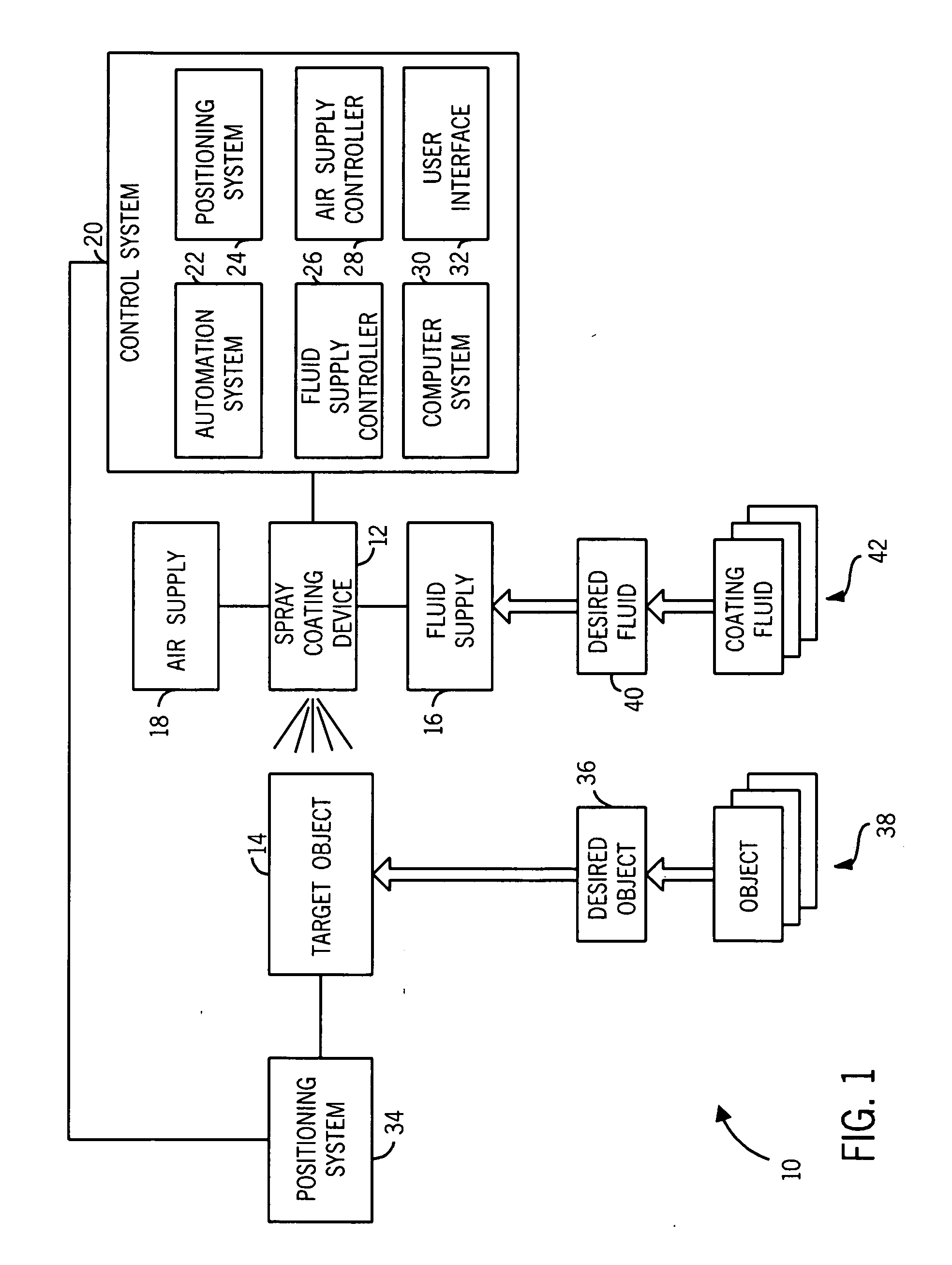
Unfortunately, these curing rooms are costly in terms of space consumption within the facility, and the curing rooms are incapable of focusing heat on specific regions of the product.
Unfortunately, the size, shape, weight, position, or complexity of the target object, the arm, or the heater often complicates the user's ability to orient the heater in the desired position relative to a surface material to be cured.
In addition, the electrical wires may block, restrict, jam, or generally complicate movement of the arm.

Method used


Image

  • System and method having arm with cable passage through joint to infrared lamp
  • System and method having arm with cable passage through joint to infrared lamp
  • System and method having arm with cable passage through joint to infrared lamp

Examples


Embodiment Construction

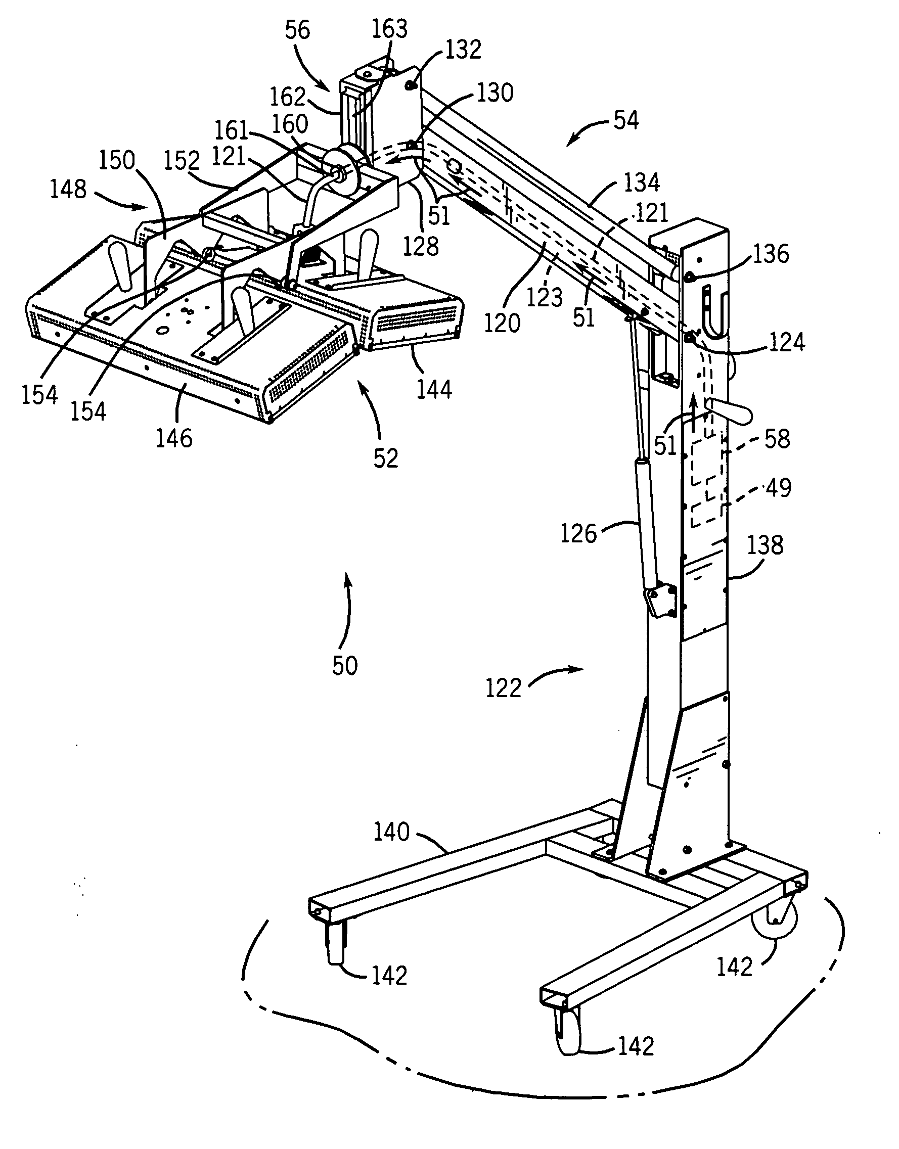
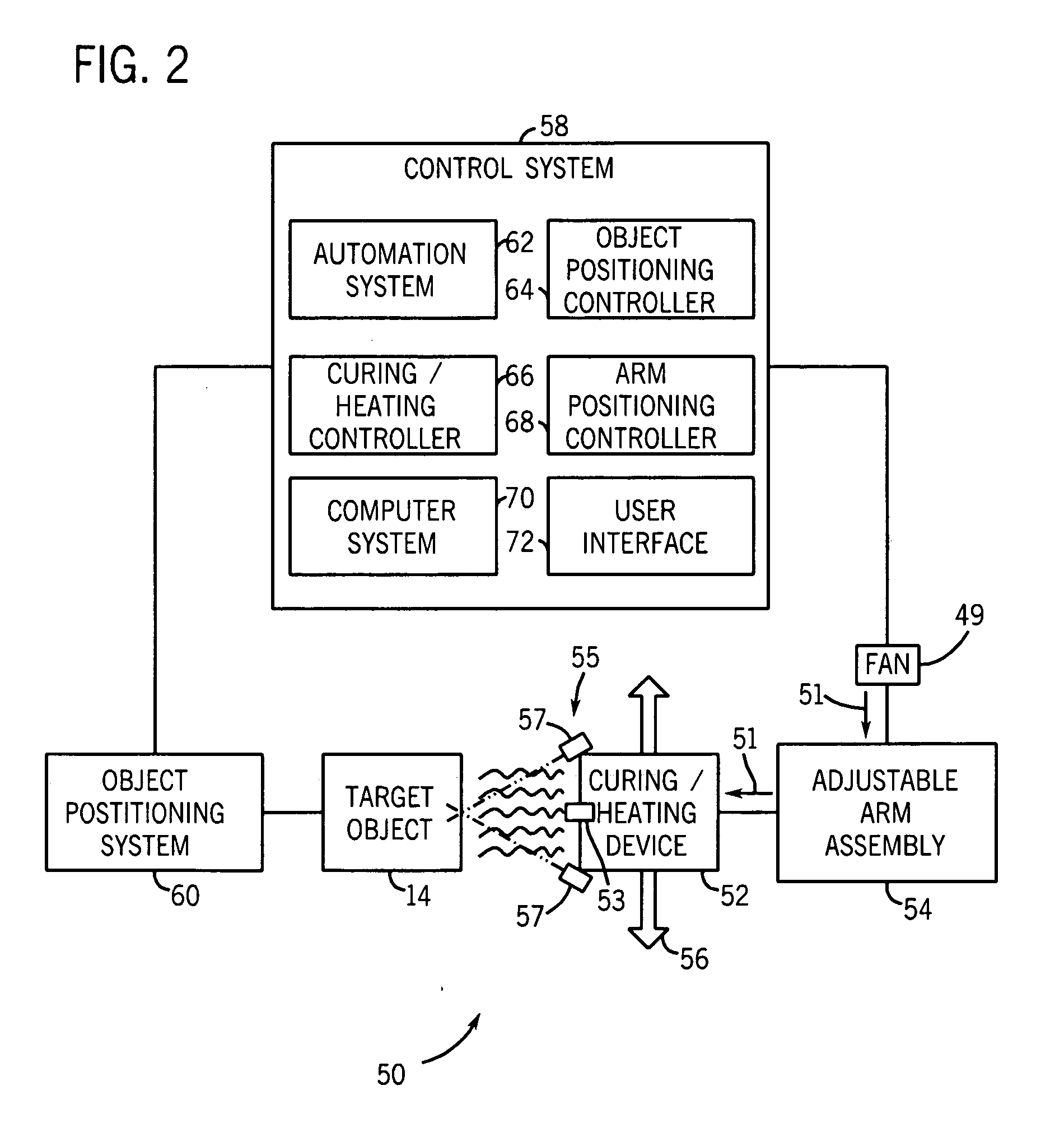
[0025]As discussed in detail below, embodiments of an adjustable arm are used to position a curing device, such as an infrared heating lamp, in a desired orientation to heat, dry, or generally cure a surface material (e.g., paint, primer, clear coat, decals, stain, and other finish coatings) on a variety of target objects (e.g., vehicles, furniture, fixtures, and other products). In certain embodiments, the adjustable arm has one or more internal cable passageways to route electrical and / or control cables to the curing device. In addition, the adjustable arm may include one or more joints, such as adjustable friction joints, which include one or more internal cable passageways. Thus, the electrical and / or control wires may be at least substantially or entirely concealed within the adjustable arm and joints. In this manner, the wires are generally protected from potential damage or disconnection during use of the adjustable arm, while the adjustable arm is able to move without potent...


PUM


Abstract

In one embodiment, a system is provided with a rotatable arm having a movable joint, an infrared lamp coupled to the rotatable arm, and an electrical cable extending through the rotatable arm and the movable joint. In another embodiment, a system is provided with a base and an arm coupled to the base via a first rotatable joint, wherein the arm has an arcuate shape. The system also may include a head coupled to the arm via a second rotatable joint, an infrared lamp coupled to the head, and a temperature sensor disposed adjacent the infrared lamp. Furthermore, the system may include an air flow passage extending through the first rotatable joint, the arm, and the second rotatable joint. A fan also may be pneumatically coupled to the air flow passage. In addition, an electrical cable may be disposed in the air flow passage, wherein the electrical cable extends to the infrared lamp and the temperature sensor.

Description

CROSS REFERENCE TO RELATED APPLICATION[0001]This application claims priority to U.S. Provisional Patent Application No. 60 / 816,770, filed on Jun. 27, 2006, which is hereby incorporated by reference.BACKGROUND[0002]The present technique relates generally to finishing systems and, more particularly, to industrial finish curing systems.[0003]Finish coatings, such as paint, are often applied to a product and subsequently cured via heating devices. In many finishing systems, the product is placed in a curing room, where heat is flowed through the room to dry the finish coatings that were applied to the product. Unfortunately, these curing rooms are costly in terms of space consumption within the facility, and the curing rooms are incapable of focusing heat on specific regions of the product.[0004]In certain applications, a heater is coupled to a mechanical arm, which is manually moved to a desired position relative to the target product. In this manner, heat can be focused on specific re...

Claims


Application Information

Patent Timeline
Patent Type & Authority Applications(United States)
IPC IPC(8): G06F19/00
CPCF26B3/30H05B3/0052H05B3/0038F26B2210/12B05D3/02B05D3/06
Inventor NELSON, JAMES S.REKUCKI, MARK A.
Owner CARLISLE FLUID TECH INC
Learn More