

Reference electrode, salt bridge and ionic concentration measuring device by the use of reference electrode and salt bridge
a technology of reference electrode and reference electrode, which is applied in the direction of instruments, material electrochemical variables, non-aqueous electrolyte cells, etc., can solve the problems of contaminating sample solution, liquid junction is blocked, and the variation of liquid junction potential cannot be completely eliminated, so as to prevent the permeation of the membrane, high accuracy, and high durability
- Summary
- Abstract
- Description
- Claims
- Application Information
AI Technical Summary
Benefits of technology
Problems solved by technology
Method used
Image

Examples
first embodiment
[0037] A reference electrode in accordance with a first embodiment of the present claimed invention will be described by reference to the accompanying drawings.
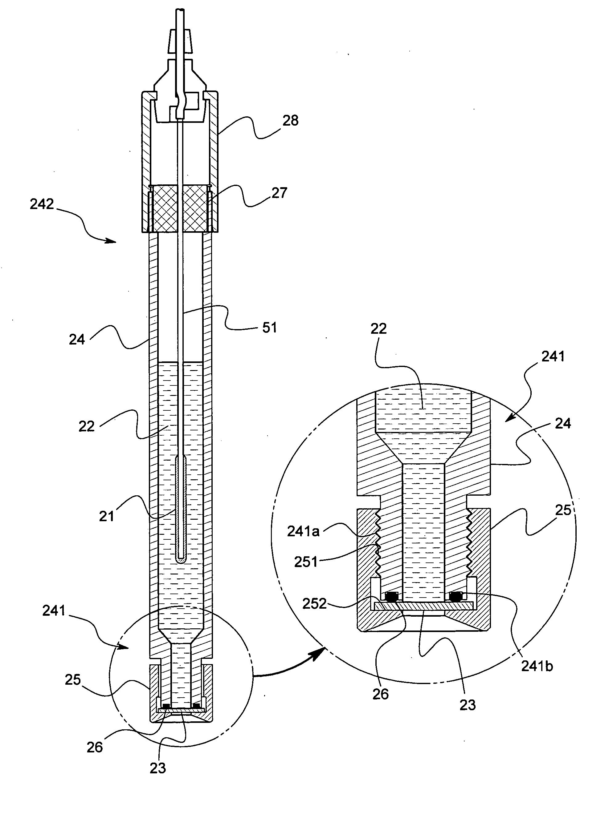
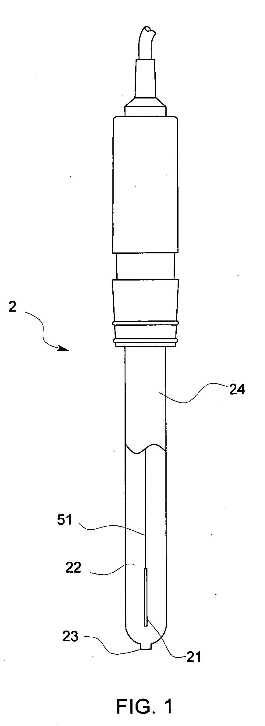
[0038] The reference electrode 2 in accordance with this embodiment comprises, as shown in FIG. 1, a cylindrical support tube 24 made of glass and a liquid junction 23 that is connected with a distal end portion of the support tube 24. In the support tube 24 an internal electrode 21 is accommodated and an internal solution 22 is filled. A lead wire 51 is connected to the internal electrode 21 and the lead wire 51 extends outside from a proximal end portion of the support tube 24 so as to be connected with a body of a pH meter, not shown in drawings.
[0039] The internal electrode 21 of the reference electrode 2 comprises, for example, Ag / AgCl, Hg / Hg2Cl2, Hg / Hg2SO4 or the like.
[0040] In case that the internal electrode 21 consists of, for example, Ag / AgCl, a solution containing Cl− can be used as the internal solution 22 and ...
second embodiment
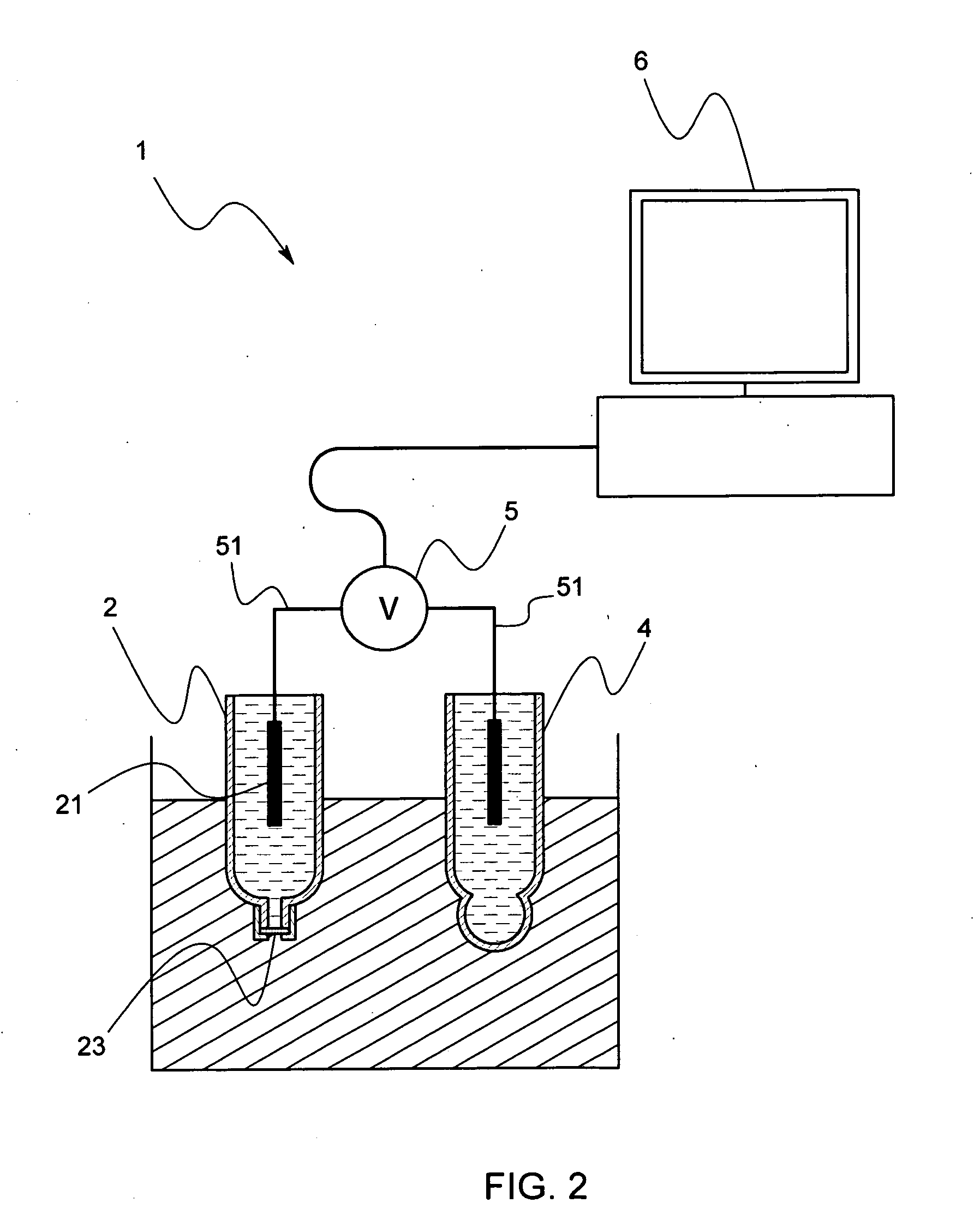
[0059] Next, an ionic concentration measuring device by the use of a reference electrode in accordance with a second embodiment of this invention will be described by reference to FIG. 2, FIG. 3 and FIG. 4.
[0060] The ionic concentration measuring device 1 in accordance with this embodiment is to measure a hydrogen-ion concentration (pH) in a sample solution and comprises, as shown in FIG. 2, a reference electrode 2, an electrode for measurement 4, a potentiometer 5 that detects a potential difference generated at a time when the reference electrode 2 and the electrode for measurement 4 are immersed into the sample solution, and an operational unit 6 that calculates and displays the ionic concentration based on the potential difference detected by the potentiometer 5.
[0061] A pH electrode is used in this embodiment as the electrode for measurement 4, and an ion selective electrode may be used.
[0062] The reference electrode 2 comprises, as shown in FIG. 2, a cylindrical support tub...
other modified embodiment
[0077] The present claimed invention is not limited to the above-mentioned embodiments. The liquid junction 23 may be formed by connecting a minute cylindrical member made of glass to the distal end portion 241 of the support tube 24 made of glass and filling the gelled hydrophobic ionic liquid in the cylindrical member without using a porous material such as glass or ceramics for the liquid junction 23.
[0078] In addition, the gelled hydrophobic ionic liquid filled in the tiny cylindrical member may be sandwiched between plate shaped bodies made of a porous material such as a cellulose dialysis membrane, a millipore filter, an ion exchange membrane, glass or ceramics, or the above-mentioned membrane or the porous material may be placed only at an interface between the hydrophobic ionic liquid and the sample solution.
[0079] Furthermore, the internal solution 22 may be gelled. As a method for gelling the internal solution 22, the same method as the method for gelling the hydrophobic...
PUM
 Abstract
Description
Claims
Application Information