
Flexible Wall Having Fire Resistant Properties

Inactive Publication Date: 2008-01-03
GOLDFIRE
View PDF9 Cites 36 Cited by
  • Summary
  • Abstract
  • Description
  • Claims
  • Application Information

AI Technical Summary

Benefits of technology

[0009]One object of the invention is to provide a

Problems solved by technology

There are many problems with the use of water-based mixtures.
The installation is complex because it requires a tank and a pump.
Also, the use of water is often incompatible with the electrical, electronic or computer equipment present in many rooms requiring prote

Method used


Image

  • Flexible Wall Having Fire Resistant Properties
  • Flexible Wall Having Fire Resistant Properties
  • Flexible Wall Having Fire Resistant Properties

Examples


Example

[0024]These and other aspects of the invention will be clarified in the detailed description of certain embodiments of the invention, reference being made to the following figures:

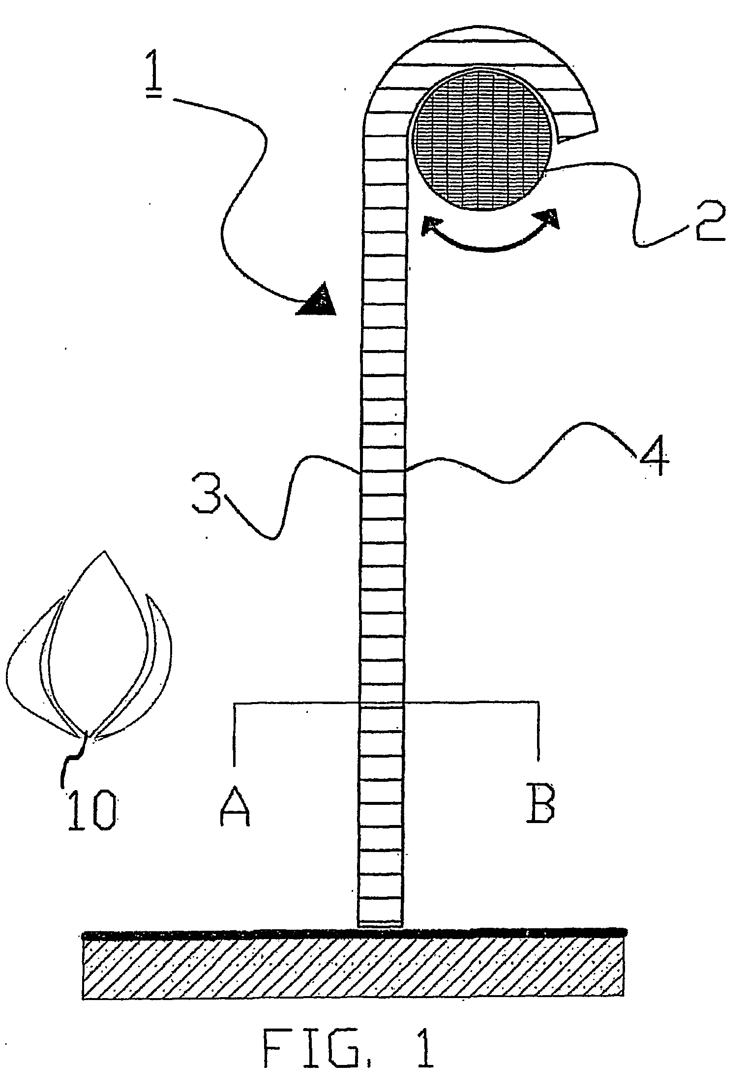
[0025]FIG. 1 shows an example of a fire-resistant flexible wall; the wall is hung from and fixed to a horizontal shaft;

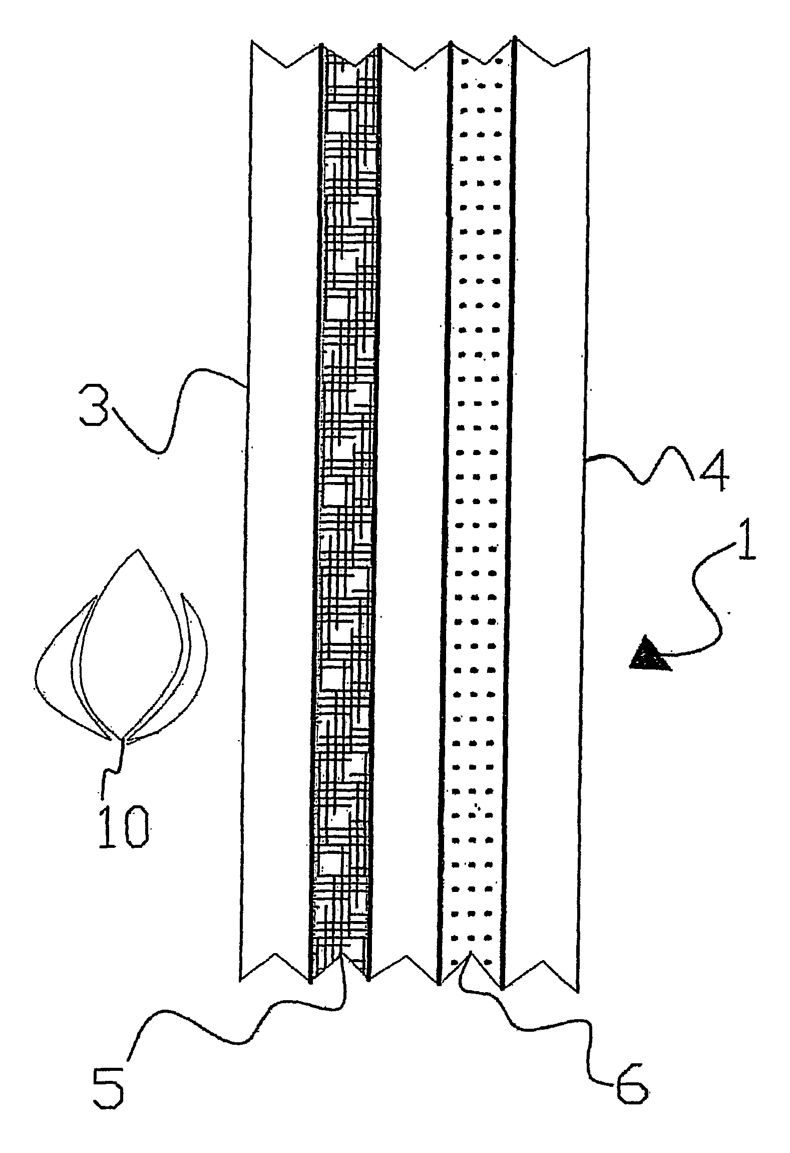
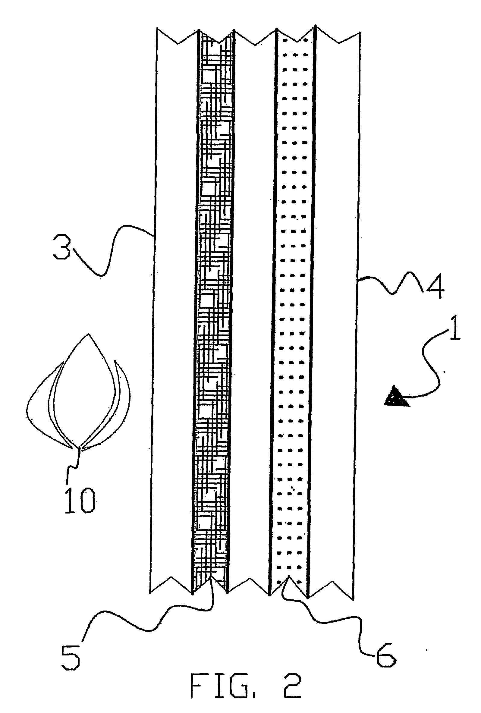
[0026]FIG. 2 is a cross section A-B through the wall shown in FIG. 1 in one embodiment of the invention;

[0027]FIG. 3 is a cross section A-B through the wall shown in FIG. 1, in a preferred embodiment of the invention; and

[0028]FIG. 4 is a cross section A-B through the wall shown in FIG. 1, in another preferred embodiment of the invention.

[0029]The figures are not drawn to scale. Generally speaking, similar parts are indicated by similar references from one figure to another.

[0030]FIG. 1 is a diagram of a fire-resistant flexible wall (1) hung from and fixed to a horizontal shaft (2) which can be rotated to wind the wall (1). This wall (1) has a first surface (3) designed to be presented to ...


PUM


Abstract

The invention concerns a fire-resistant flexible wall, comprising a first surface facing towards the fire, and an insulating material layer provided between a basalt fabric layer and a second surface opposite the first surface. The wall may comprise a second basalt fabric layer provided between the insulating material layer and the second surface. The wall may further comprise a continuous metal layer. Each layer plays a specific role (mechanical or fire resistance, thermal insulation, smoke shield or gas shield) and enables walls of large dimensions and high efficiency to be produced.

Description

FIELD OF THE INVENTION[0001]In the field of fire-resistant walls, a distinction may be made between rigid walls and flexible walls. Rigid walls are made essentially of rigid materials and generally have little deformability.[0002]The invention relates to fire-resistant flexible walls, that is, walls made essentially of flexible materials. This property of flexibility allows them to be deployed and folded away easily, and in particular without requiring any segmentation of the wall. Such segmentation is adopted in certain rigid walls, such as those constructed by assembling a number of rigid sections hinged together to form a roller shutter.[0003]The flexible walls discussed in the present text may for example form a retractable curtain, or a roller blind, or be installed in a fixed manner.[0004]Fire resistance is the result of the action of a material which, when interposed between the fire and a zone to be protected, prevents or reduces the propagation of fire towards the zone to b...

Claims


Application Information

Patent Timeline
IPC IPC(8): A62C2/10
CPCA62C2/10
Inventor GOLDBERG, SIMON
Owner GOLDFIRE
Learn More