Distinguishing reference image errors in optical inspections

Inactive Publication Date: 2008-01-03
FIEKOWSKY PETER
View PDF7 Cites 8 Cited by
  • Summary
  • Abstract
  • Description
  • Claims
  • Application Information

AI Technical Summary

Benefits of technology

[0010]This invention describes a method for detecting defects in a reference image thereby reducing the frequency of false defects and increasing the efficiency of optical inspections. This method is described as used in semiconductor photomask inspection, but is also applicable to other image-based inspections, such as inspection of printed material where accuracy is critical, e.g., printed circuit boards, pharmaceutical labels and other documents.
[0011]The method is based on the assumption that defects are more random than the patterns being manufactured. Thus, if the reference image is more random (less symmetrical) than the suspect defect region of the test image, then the defect is in the reference image. Of course this does not prove that there is no defect in the test image, but it reduces the probability of a test image defect typically by a factor of a billion.

Problems solved by technology

Of course this does not prove that there is no defect in the test image, but it reduces the probability of a test image defect typically by a factor of a billion.

Method used


Image

  • Distinguishing reference image errors in optical inspections
  • Distinguishing reference image errors in optical inspections
  • Distinguishing reference image errors in optical inspections

Examples


Embodiment Construction

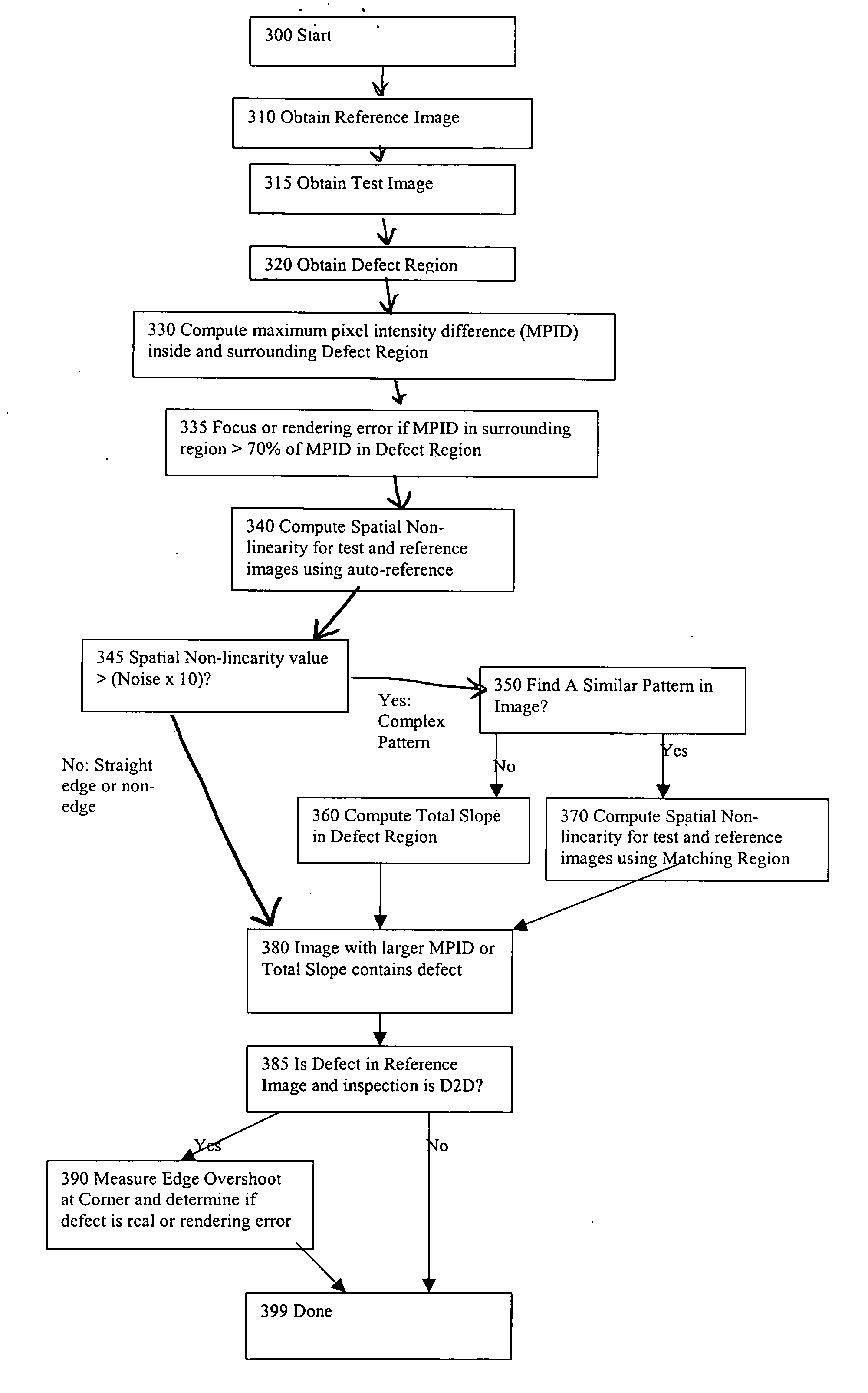
[0026]The method begins at 300 by receiving the images into a computer system for analysis. The test and reference images are acquired along with the defect region in steps 310 and 315. The reference image may be obtained in step 310 from any of the sources previously described, namely, 1) an image of a similar structure that is presumed defect free, 2) a computer rendering of the design data for the pattern being inspected, or 3) an alternate imaging method of the actual pattern being inspected. Devices that are used to produce this reference image include the KLA SLF, KLA 5xx, Orbot 8000 and NEC LM7000B inspection tools.

[0027]The test image may be obtained in step 315 from a photomask inspection system, generally the same inspection system that produced the reference image. Both images are typically grayscale and transferred via file from the inspection tool to the image analysis software, such as the software that may embody the steps herein described. Alternatively, the images m...


PUM


Abstract

Detecting defects in reference images used for optical inspections reduces false defect detections in the test image. Reference images are presumed perfect, but in practice contain defects. Defects in the reference image are detected by measuring the symmetry or randomness of pixels in the area of the suspected defect in both images. Measurements of the pixel intensity ranges, edge smoothness, and total edge slope in the two images are compared to determine if a suspect defect is actually in the reference image.

Description

FIELD OF THE INVENTION[0001]The present invention relates generally to optical inspections. More specifically, the present invention relates to detecting defects in reference images in microlithography.BACKGROUND OF THE INVENTION[0002]In the field of optical inspections, especially in microlithography, inspections are performed by comparing a sample or test image to a reference image and detecting differences. Reference images are presumed perfect, but in practice contain defects. Undetected defects in the reference image cause spurious or false defect detections in the test image.[0003]The test image commonly comes from an optical system similar to a microscope with a camera. In the field of photographic mask (photomask) inspection in semiconductor microlithography, the test image can come from other sources of two-dimensional images, such as, but not limited to a SEM (scanning electron microscope) or an AFM (atomic force microscope). The reference image commonly comes from one of ...

Claims


Application Information

Patent Timeline
IPC IPC(8): G06K9/00
CPCG06T7/0004G03F1/84
Inventor FIEKOWSKY, PETER
Owner FIEKOWSKY PETER
Why Eureka
Try Eureka