
Image forming apparatus

a technology of forming apparatus and forming tape, which is applied in the direction of electrographic process apparatus, instruments, optics, etc., can solve the problems of uneven thickness of endless belt, and damage to endless belt, so as to prevent crack formation and improve the durability of endless belt

Active Publication Date: 2008-01-03
OKI ELECTRIC IND CO LTD
View PDF3 Cites 2 Cited by
  • Summary
  • Abstract
  • Description
  • Claims
  • Application Information

AI Technical Summary

Benefits of technology

[0012]In the present invention, the belt has the edge surface having the step portion of less than 0.05 mm and the ten-point mean roughness (Rz) of equal to or smaller than 5.0 μm. Accordingly, when the belt moves, it is possible to prevent a crack form forming in an edge of the belt, thereby improving durability of the belt.

Problems solved by technology

In the conventional image forming device, it is troublesome to put the reinforcing tape on the endless belt.
Once the reinforcing tape comes off, the endless belt directly receives a stress due to repetitive deformation, so that the endless belt is damaged from the edge thereof and cracked, and even broken later.
As a result, durability of the endless belt is impaired.

Method used


Image

  • Image forming apparatus
  • Image forming apparatus
  • Image forming apparatus

Examples


first embodiment

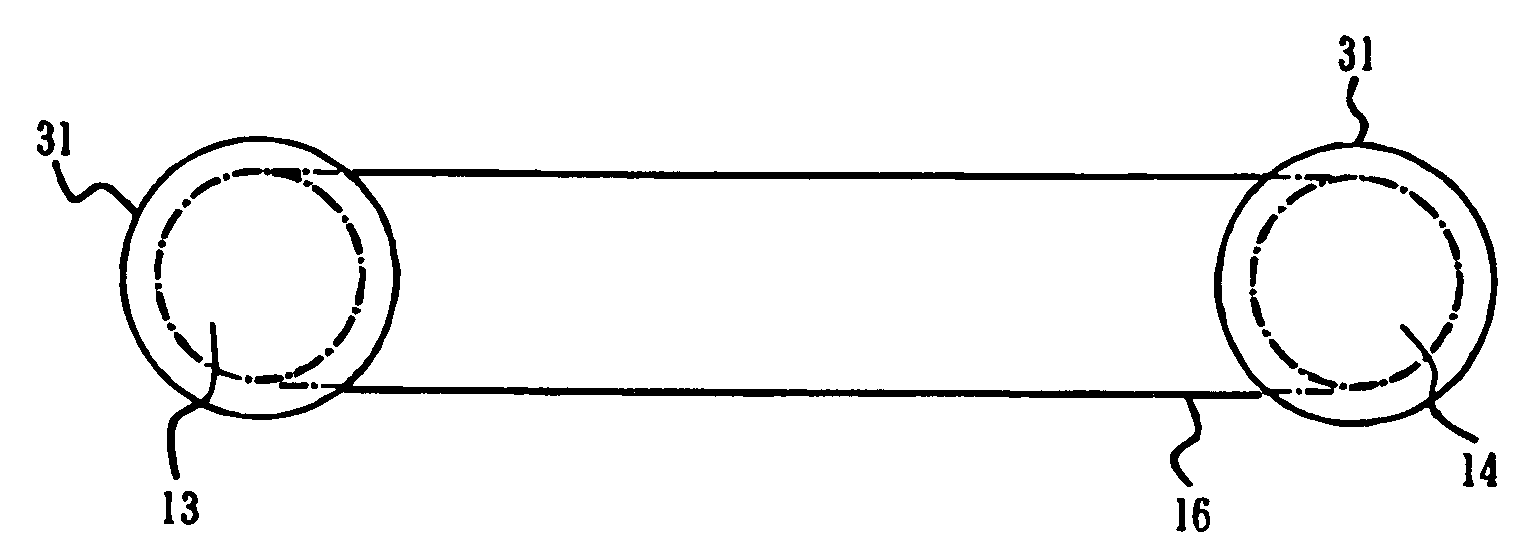
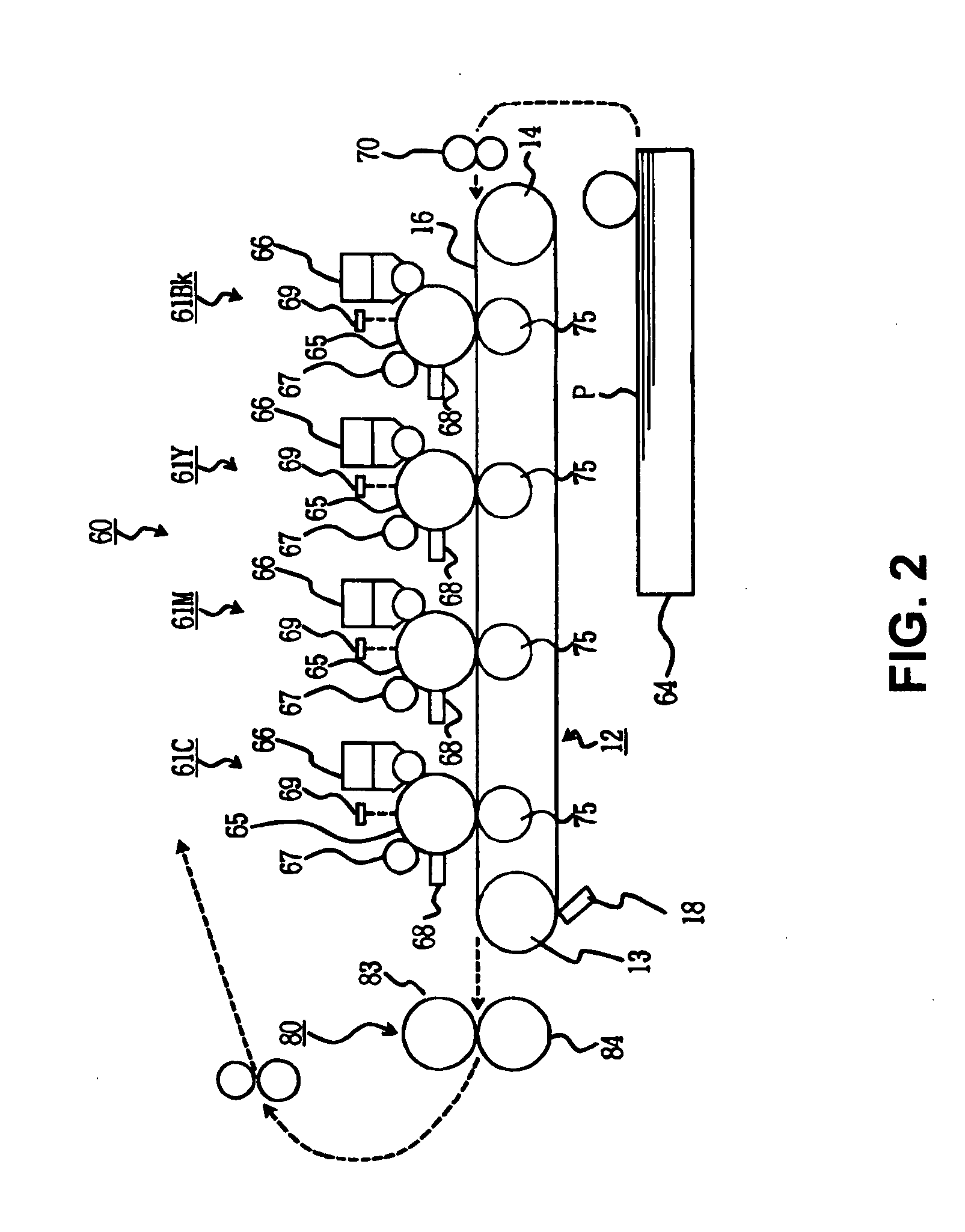
[0026]FIG. 2 is a schematic view showing a printer 60 according to the first embodiment of the present invention. As shown in FIG. 2, the printer 60 has image forming units 61Bk, 61Y, 61M, and 61C for forming a toner image as a developer image in each color, i.e. black, yellow, magenta, and cyan; a transfer device 12 arranged facing the image forming units 61Bk, 61Y, 61M, and 61C for forming a transfer region in each color with respect to the image forming units 61Bk, 61Y, 61M, and 61C, and for transferring a toner image in each color to a sheet or a record medium; a sheet cassette 64 as a print medium supplying unit for feeding a sheet P to each transfer region; a register roller 70 for supplying the sheet P from the sheet cassette 64 at a proper timing when an image is formed at the image forming units 61Bk, 61Y, 61M and 61C; and a fuser 80 as a fixing device for fixing a color toner image to the sheet P after transferring the image in each transfer region. The fuser 80 has a heat...

second embodiment

[0060]A second embodiment of the invention will be described below. Components in the second embodiment similar to those in the first embodiment are designated by the same reference numerals, and explanations thereof are omitted. The components in the second embodiment similar to those in the first embodiment provide effects similar to those in the first embodiment.

[0061]FIG. 7 is a schematic view showing a printer according to the second embodiment of the present invention. FIG. 8 is a schematic front view showing a belt device according to the second embodiment of the present invention.

[0062]In the embodiment, the endless belt 16 is tensely placed around the driving roller 13 as a first roller; the idle roller 14 as a second roller; and a tension roller 88 as a third roller, so that the endless belt 16 runs in an arrow direction. The tension roller 88 and the transfer roller 89 are arranged with the endless belt 16 inbetween, and the sheet P as a record medium is fed between the e...

third embodiment

[0063]A third embodiment of the present invention will be described below. Components in the third embodiment similar to those in the first and second embodiments are designated by the same reference numerals, and explanations thereof are omitted. The components in the third embodiment similar to those in the first and second embodiments provide effects similar to those in the first and second embodiments.

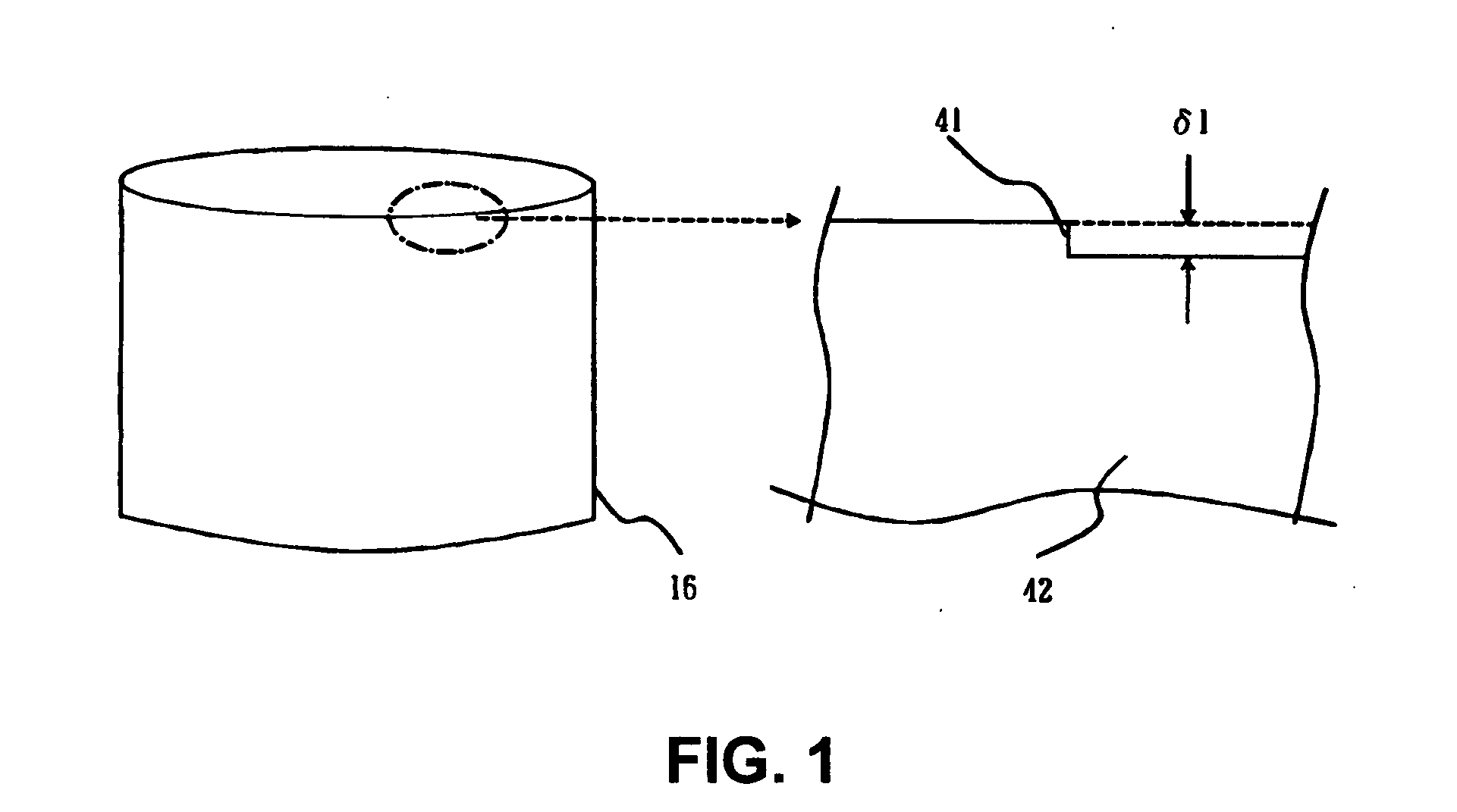
[0064]FIG. 9 is a schematic cross-sectional view No. 1 of the edge surface 45 of the endless belt 16 according to a third embodiment of the present invention. FIG. 10 is a schematic cross-sectional view No. 2 of the edge surface 45 of the endless belt 16 according to the third embodiment of the present invention. FIG. 11 is a cross-sectional view No. 3 of the edge surface 45 of the endless belt 16 according to the third embodiment of the present invention. FIG. 12 is a cross-sectional view No 4 of the edge surface 45 of the endless belt 16 according to the third embodiment of the p...


PUM


Abstract

An image forming apparatus includes a first roller; a second roller; a belt tensely provided between the first roller and the second roller; and a guiding member for guiding an edge of the belt. Further, the belt has an edge surface having a step portion of equal to or smaller than 0.05 mm and a ten-point mean roughness (Rz) of equal to or smaller than 5.0 μm.

Description

BACKGROUND OF THE INVENTION[0001]1. Field of the Invention[0002]The present invention relates to an image forming apparatus.[0003]2. Description of Related Art[0004]A conventional electro-photographic image forming apparatus such as a printer, a copier, a fax machine, and a multifunction machine thereof forms an image through the following process. In a case of, for example, the printer, a surface of a photosensitive drum or an image supporting member is charged with a charging roller. Then, an LED head exposes the surface of the photosensitive drum to form a latent image. A developing roller electrostatically attaches a thin layer of toner to the latent image to form a toner image; and a transfer roller transfers the toner image to a sheet, thereby forming an image or printing. After transferring the toner image, a cleaning blade cleans toner remaining on the photosensitive drum. Afterward, the sheet with the toner image transferred thereon is sent to a fixing device, thereby fixin...

Claims


Application Information

Patent Timeline
Patent Type & Authority Applications(United States)
IPC IPC(8): G03G15/00
CPCG03G15/1685G03G15/162G03G2221/1642G03G2215/1623
Inventor ITO, MICHIAKI
Owner OKI ELECTRIC IND CO LTD
Learn More