
Gloss applicator and image forming apparatus including same

Inactive Publication Date: 2013-07-04
RICOH KK
View PDF6 Cites 7 Cited by
  • Summary
  • Abstract
  • Description
  • Claims
  • Application Information

AI Technical Summary

Benefits of technology

The invention prevents the belt from getting too hot too quickly during cooling periods, which reduces power consumption. It also prevents the cooling member from becoming a barrier for the movement of the belt, which could cause damage to the belt and reduce its durability.

Problems solved by technology

First, because the cooling member is constantly in contact with the belt, the temperature of the belt which has passed through the heater section decreases, and, when reaching the heater section again, the belt mostly has a heat less than the temperature necessary to smooth the surface of the toner image as desired. Then, the temperature-raising time for the heater section increases and the more power consumption is required to raise the temperature of the heater section.
Second, when the cooling member remains in contact with the belt, the cooling member prevents the belt from moving freely and slippage occurs between the belt and the rollers around which the belt is wound.
For example, in a case in which a heating nip is formed using the pressure roller and the heat roller disposed in the heating section, if the belt is separated from the heat roller to prevent excessive heating of the pressure roller, the belt receives friction resistance from the cooling member due to the contact with the cooling member, resulting in slippage between the belt and the drive roller and a loss of coupled operation with the heat roller.
As a result, heating and thermal capacity applying time to the recording sheet becomes unstable and a desired glossiness cannot be obtained.
As a result, it becomes difficult to obtain a smoothness of the toner image surface smoothed by the smoothness of the belt surface.
Thus, the desired glossiness depending on the smoothness of the belt would not be obtained.

Method used


Image

  • Gloss applicator and image forming apparatus including same
  • Gloss applicator and image forming apparatus including same
  • Gloss applicator and image forming apparatus including same

Examples


first embodiment

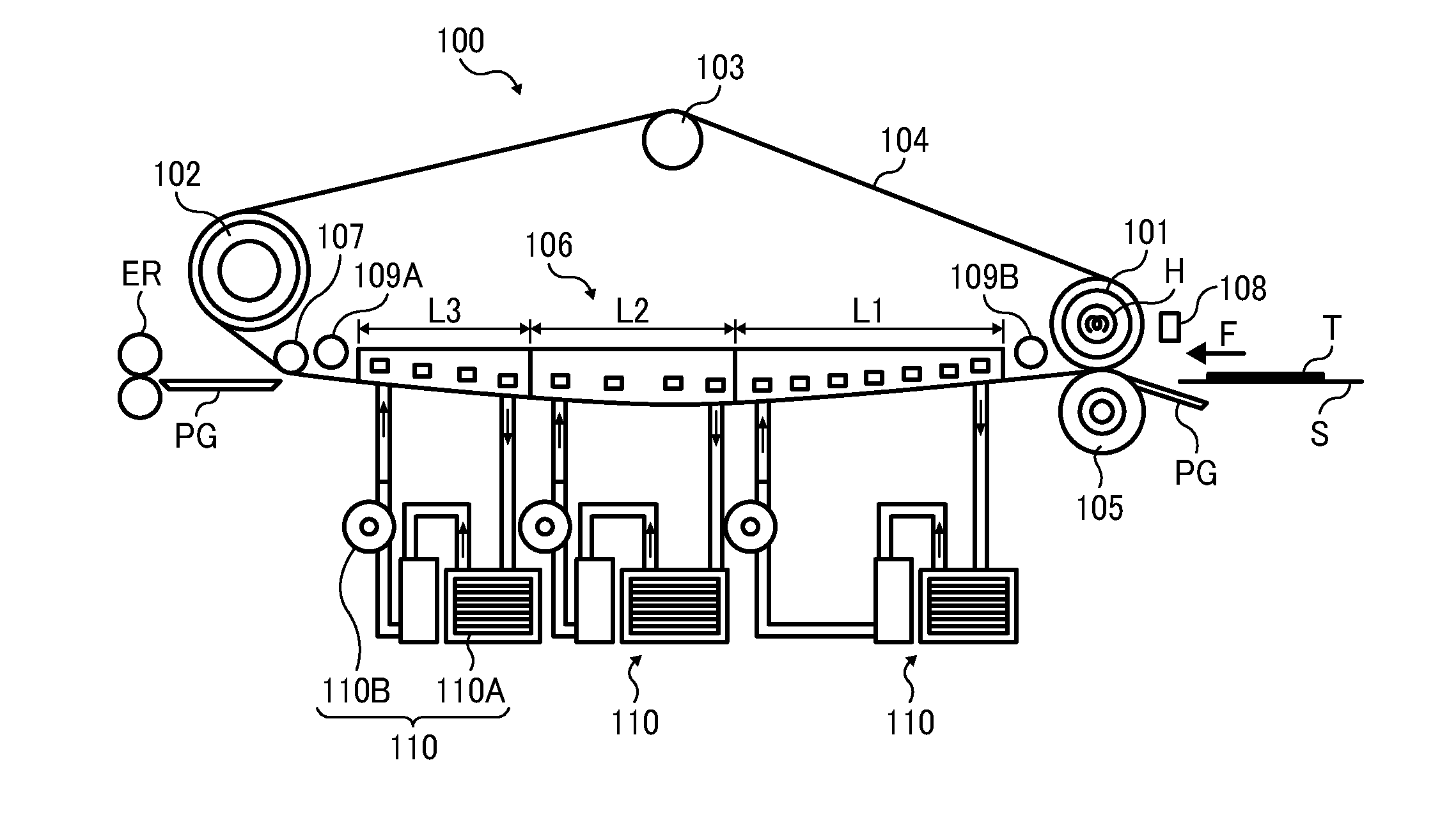
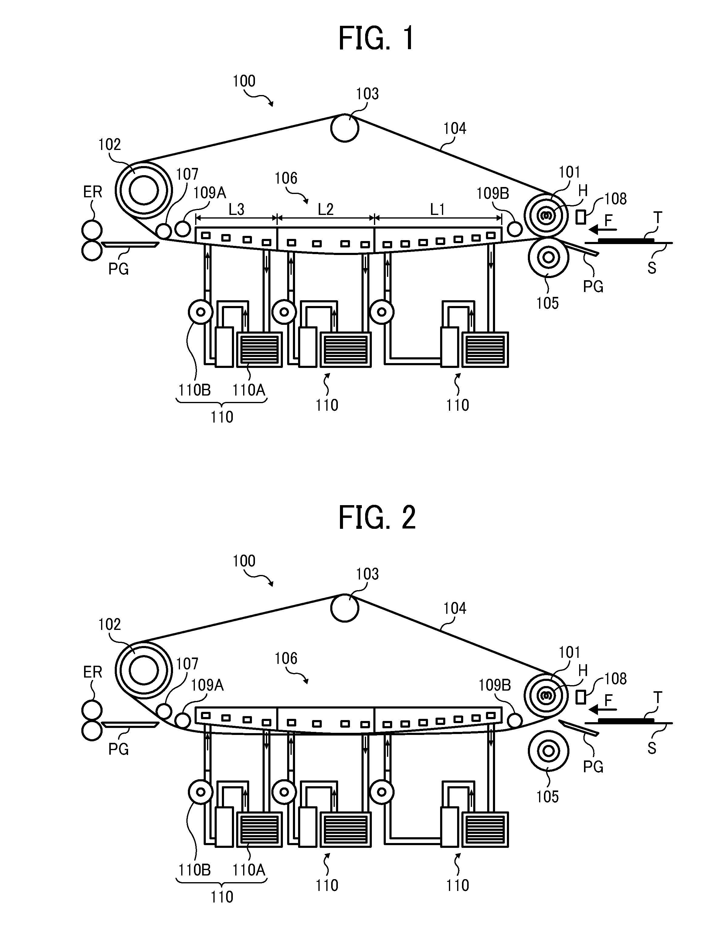
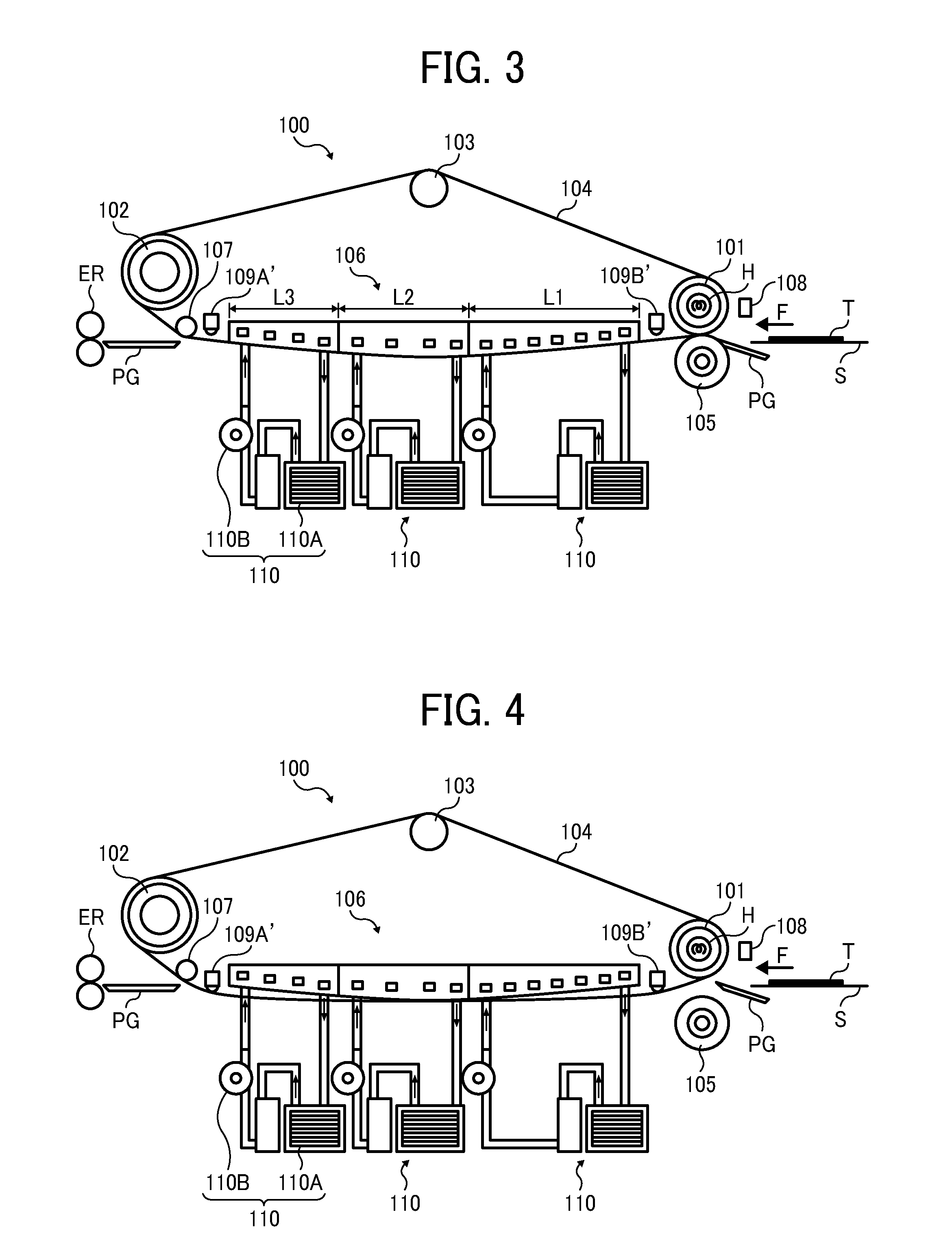
[0029]FIG. 1 shows a schematic view illustrating a structure of a gloss applicator according to the present invention.

[0030]As illustrated in FIG. 1, a gloss applicator 100 includes a heat roller 101; a drive roller 102; a tension roller 103; an endless belt 104; a pressure roller 105; and a cooling unit 106. The heat roller 101 functions as a heating member and is disposed upstream in a conveyance direction as indicated by an arrow F of a recording sheet S. The endless belt 104 is wound around the heat roller 101, the drive roller 102, and the tension roller 103, and is driven by the drive roller 102, of which a taut portion opposite the recording sheet S moves in the conveyance direction of the recording sheet S. The pressure roller 105 is disposed at a position opposite the heat roller 101 with the endless belt 104 disposed therebetween. The cooling unit 106 is disposed at an interior surface of the taut portion of the endless belt 104 opposite the recording sheet S.

[0031]As illu...


PUM


Abstract

A gloss applicator to apply a gloss to toner by heating and then forcibly cooling a toner image on a recording medium, includes: a plurality of rollers including a heat roller disposed upstream in a conveyance direction of the recording medium bearing the toner image thereon; an endless belt wound around the plurality of rollers and including a taut portion along the conveyance direction of the recording medium; a pressure roller disposed at a position opposite the heat roller sandwiching the endless belt together with the heat roller; a cooling member disposed at an interior surface of the taut portion of the endless belt; and a pair of separating members disposed at both ends of the cooling member and configured to contact and separate the endless belt to and from the cooling member so as to change an area of contact of the cooling member with the endless belt.

Description

CROSS-REFERENCE TO RELATED APPLICATION[0001]The present application claims priority from Japanese patent application number 2011-289776, filed on Dec. 28, 2011, the entire disclosure of which is incorporated by reference herein.BACKGROUND OF THE INVENTION[0002]1. Field of the Invention[0003]The present invention relates to a gloss applicator and an image forming apparatus, and more specifically relates to printed output gloss control.[0004]2. Description of the Related Art[0005]As is known, in an image forming apparatus employing an electrophotographic method, an electrostatic latent image formed on a photoreceptor or a latent image carrier is rendered visible by toner, after which the visible toner image is transferred onto a recording medium such as a recording sheet and fixed thereon, thereby obtaining printed output.[0006]Images obtained as printed output include not only monochrome images but also multi-color images such as full-color images. Concerning the appearance and color...

Claims


Application Information

Patent Timeline
IPC IPC(8): G03G15/20
CPCG03G8/00G03G15/6573G03G2215/2016G03G2215/00805G03G15/6585
Inventor SHIMADA, HIROYUKIAMITA, AKIYASU
Owner RICOH KK
Learn More