Optical imaging systems and methods

a technology of optical imaging and optical imaging, applied in the field of optical imaging, can solve the problems that surgeons may not know the exact location or the size of the operation site, and achieve the effect of improving the accuracy and accuracy of the operation si

Inactive Publication Date: 2008-01-03
GENERAL ELECTRIC CO
View PDF14 Cites 87 Cited by
  • Summary
  • Abstract
  • Description
  • Claims
  • Application Information

AI Technical Summary

Problems solved by technology

Furthermore, when operating, the surgeon may not know the exact location or size of the operation site, such as a tumor.

Method used


Image

  • Optical imaging systems and methods
  • Optical imaging systems and methods
  • Optical imaging systems and methods

Examples


Embodiment Construction

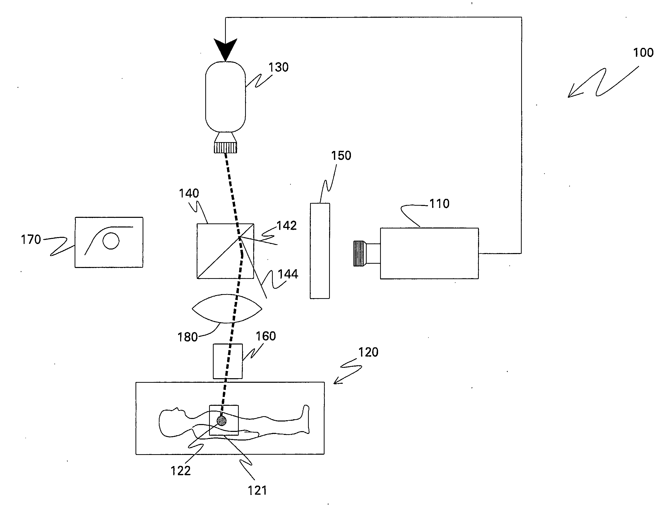
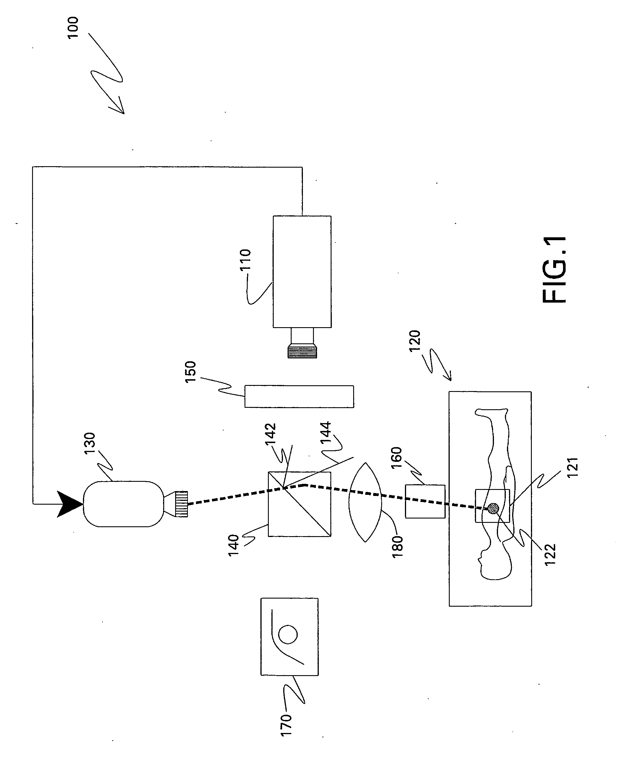
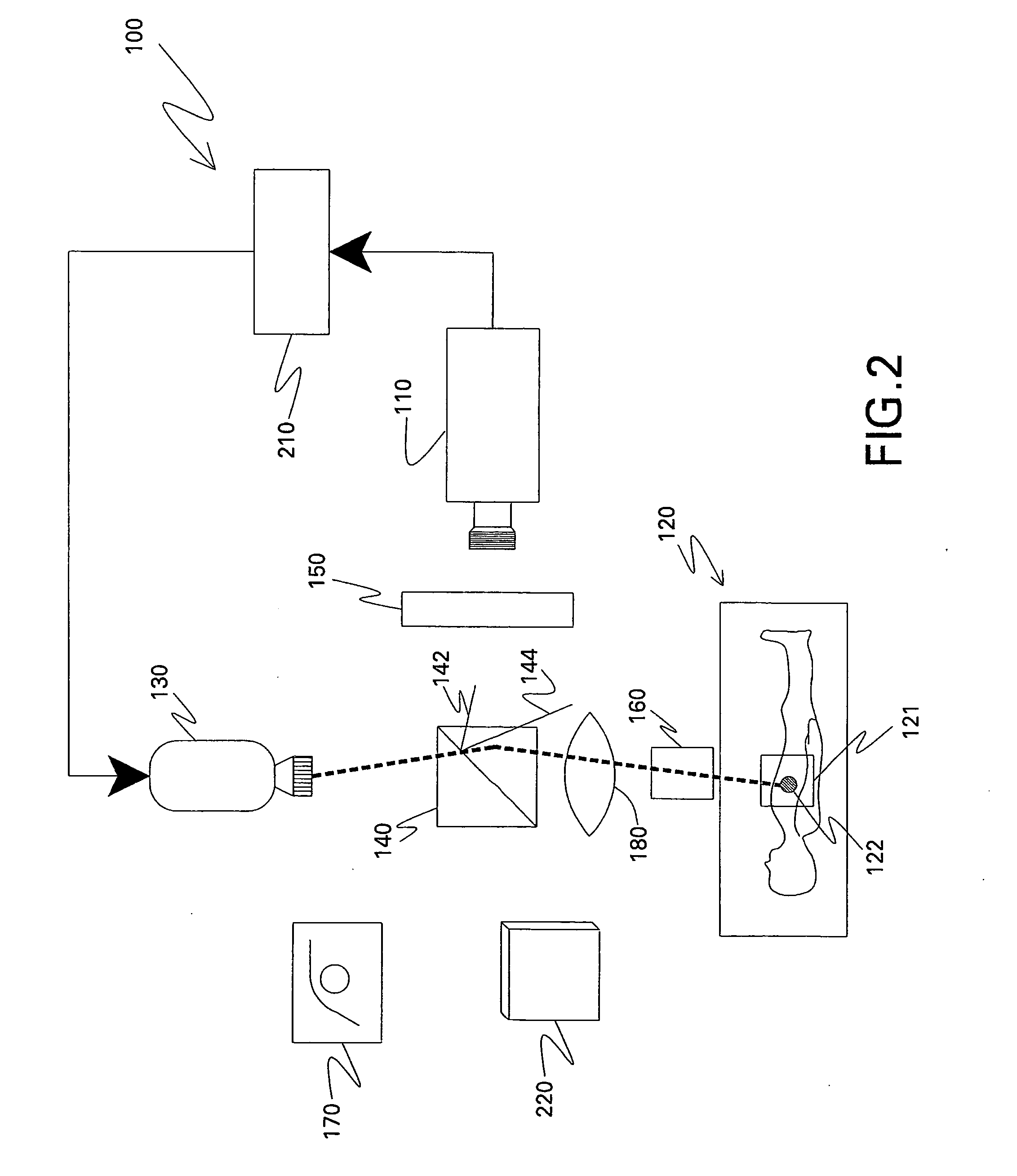
[0015]Exemplary embodiments of the invention are illustrated in the accompanying figures and examples. Referring to the drawings in general, the illustrations describe a particular embodiment of the invention and do not limit the invention thereto.

[0016]Whenever a particular embodiment of the invention is said to comprise or consist of at least one element of a group and combinations thereof, it is understood that the embodiment may comprise or consist of any of the elements of the group, either individually or in combination with any of the other elements of that group. Furthermore, when any variable occurs more than one time in any constituent or in formula, its definition on each occurrence is independent of its definition at every other occurrence. Also, combinations of parts and / or variables are permissible only if such combinations result in stable operable systems.

[0017]The methods and systems presented herein may achieve one or more of the following: projecting a visible rep...


PUM


Abstract

Optical imaging systems and methods are disclosed. The optical imaging system includes an electronic imaging device configured to capture an image of a site and a projector. An optical imaging system includes a projector configured to project a visible representation of the captured image onto the site during surgery. Another optical imaging system includes an optical element capable of aligning an optical axis of the electronic imaging device and the projector on a same optical axis. Also disclosed are methods for displaying an image on to a site. A method includes capturing a fluorescent image of a surgical site; and projecting a visible representation of the captured image onto the surgical site during surgery. Another method includes projecting a visible representation of a captured image of a site onto the site along a same optical axis along which the image is captured.

Description

BACKGROUND[0001]The invention includes embodiments that may relate to optical imaging. Particularly, the invention includes embodiments that may relate to medical imaging systems and methods.[0002]Although some optical imaging methods may be used to visualize and display a living tissue of interest, such as a surgical site, the methods indirectly visualize the surgical site by looking at a computer monitor of the surgical site, instead of directly at the surgical site. Thus, a surgeon operates by looking at a monitor instead of at the surgical site. Furthermore, when operating, the surgeon may not know the exact location or size of the operation site, such as a tumor. Consequently, a need still exists for optical imaging methods and systems.BRIEF DESCRIPTION[0003]The embodiments of the invention will be set forth and apparent from the description that follows, as well as will be learned by practice of the embodiments of the invention. Additional aspects will be realized and attained...

Claims


Application Information

Patent Timeline
Patent Type & Authority Applications(United States)
IPC IPC(8): A61B6/00
CPCA61B5/0059A61B6/508A61B5/418A61B5/415A61B90/361A61B2090/366
Inventor JANSEN, FLORIBERTUS P. M. HEUKENSFELDTLOMNES, STEPHEN JOHNSON
Owner GENERAL ELECTRIC CO
Why Eureka
Try Eureka