Multiband doherty amplifier

a doherty amplifier, multi-band technology, applied in the direction of amplifiers, dual/triple band amplifiers, amplifiers, etc., can solve the problems of insufficient gain and efficiency in the center frequency of conventional doherty amplifiers, and the 14-wave transmission line b>103/b> cannot perform the desired impedance conversion at other frequency bands, so as to achieve the effect of improving efficiency

Active Publication Date: 2008-01-10
NTT DOCOMO INC
View PDF4 Cites 17 Cited by
  • Summary
  • Abstract
  • Description
  • Claims
  • Application Information

AI Technical Summary

Benefits of technology

[0021]The present invention has been implemented in view of the above described aspects and it is an object of the present invention to provide a multiband Doherty amplifier capable of obtaining sufficient operation performance for a plurality of frequency bands.
[0024]Here, such an impedance converter sets the load impedance at the output port of the carrier amplifier to an identical value for the N (N≧2) frequencies. In this way, it is possible to cause the carrier amplifier to operate optimally for the N frequencies and consequently realize a Doherty amplifier capable of performing operation with sufficient gain and efficiency for a plurality of frequency bands. Furthermore, connecting the delay element having the same electric length as that of the impedance converter in parallel to the impedance converter allows delays of signals by the impedance converter to be corrected.
[0027]Using such a combiner allows the load impedance at the joint to be set to an equal value with respect to the above described N frequencies. This allows the carrier amplifier to be operated more optimally for the N frequencies and can consequently realize a Doherty amplifier capable of sufficient gain and efficiency operation for a plurality of frequency bands.
[0029]This leads that it is important for the multiband Doherty amplifier to improve in the efficiency when the peak amplifier is ON.

Problems solved by technology

Therefore, the ¼-wave transmission line 103 does not perform the desired impedance conversion at other frequency bands.
Therefore, the conventional Doherty amplifier 100 is unable to operate with sufficient gain and efficiency in a frequency band at a center frequency other than the design frequency (except the case where βL in Equation (1) is an even multiple of π / 2).

Method used


Image

  • Multiband doherty amplifier
  • Multiband doherty amplifier
  • Multiband doherty amplifier

Examples


Embodiment Construction

[0047]Hereinafter, embodiments of the present invention will be explained with reference to the attached drawings.

[Configuration]

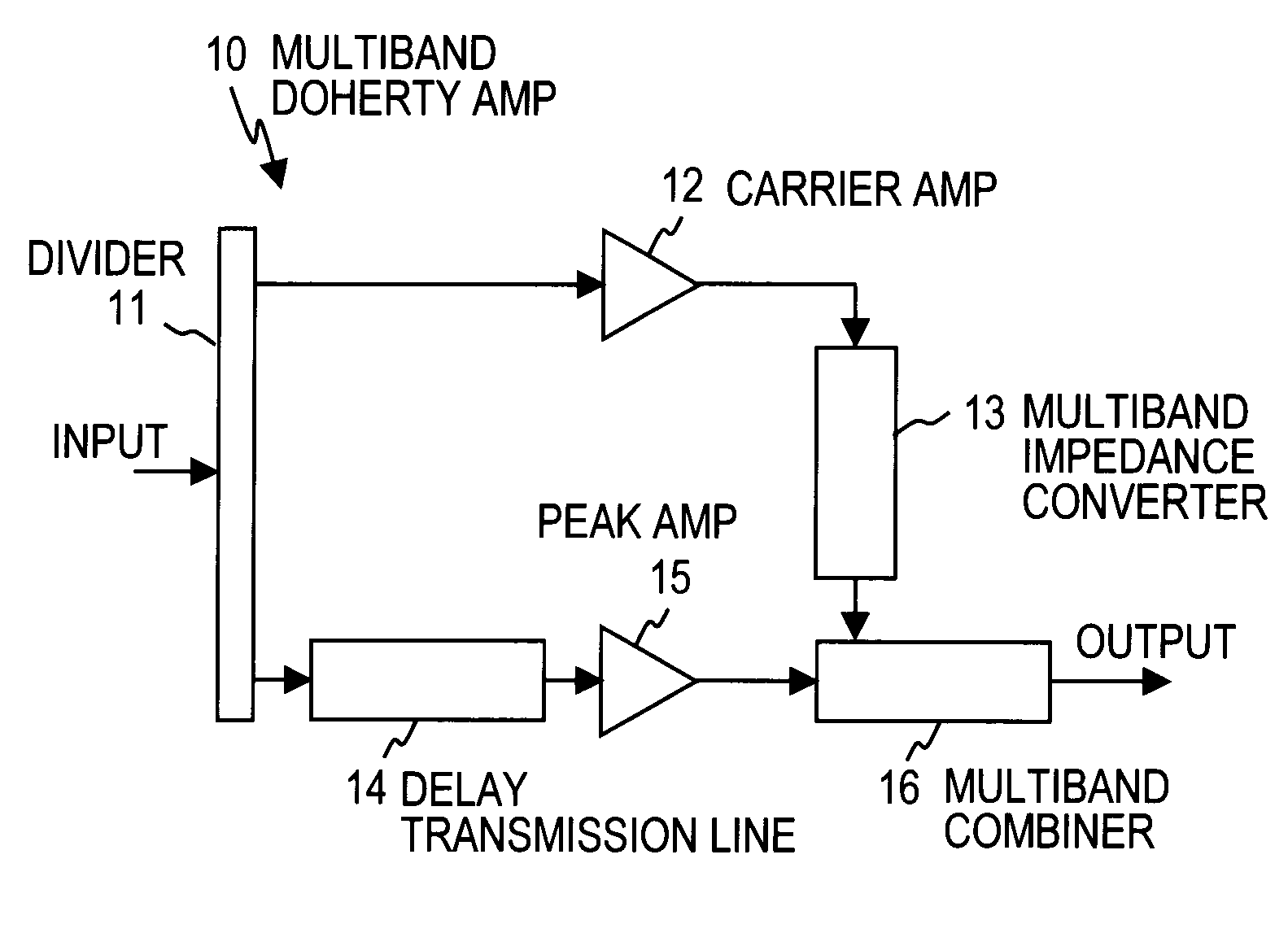
[0048]FIG. 1 is a block diagram illustrating the configuration of a multiband Doherty amplifier 10 according to the present invention.

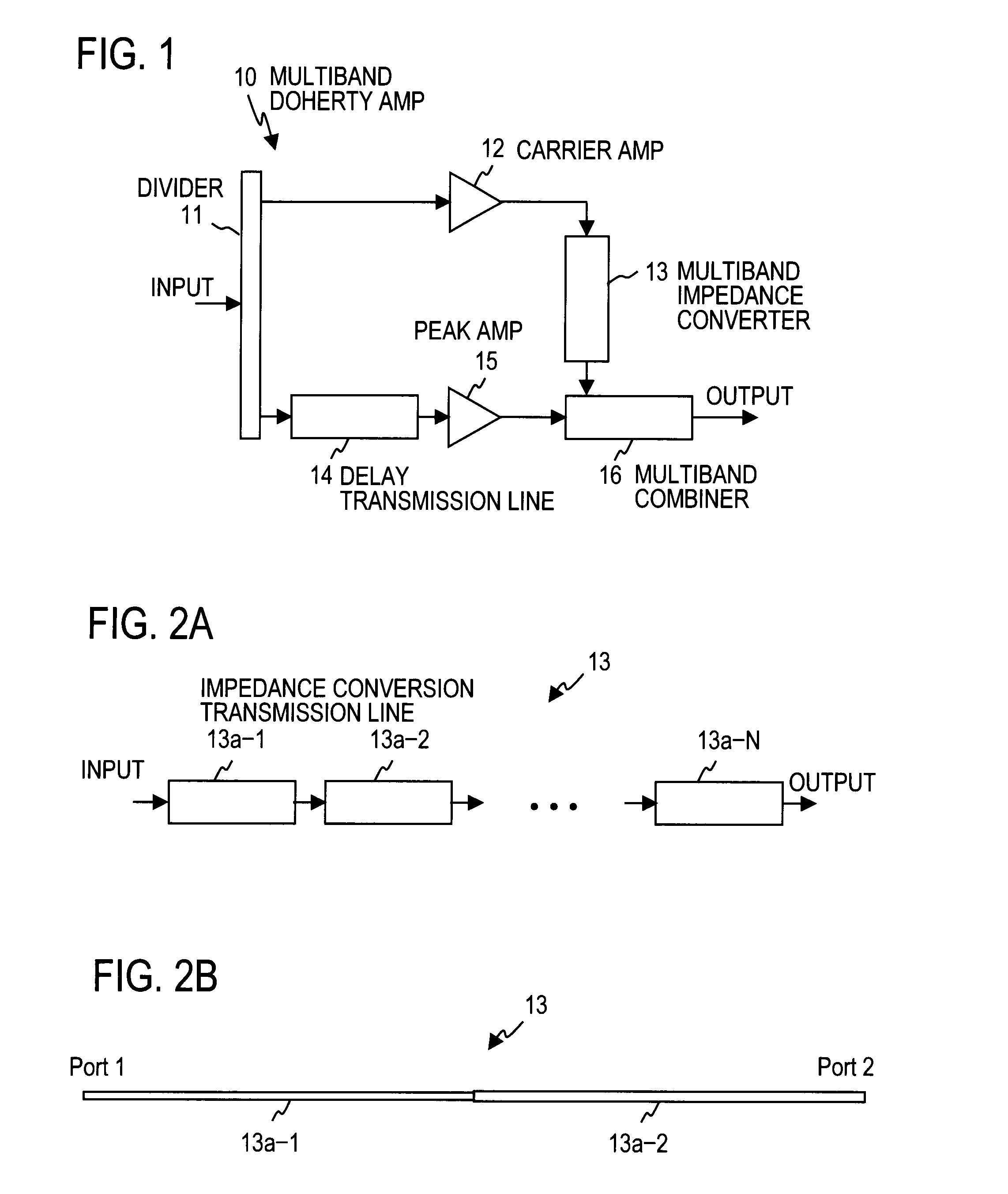
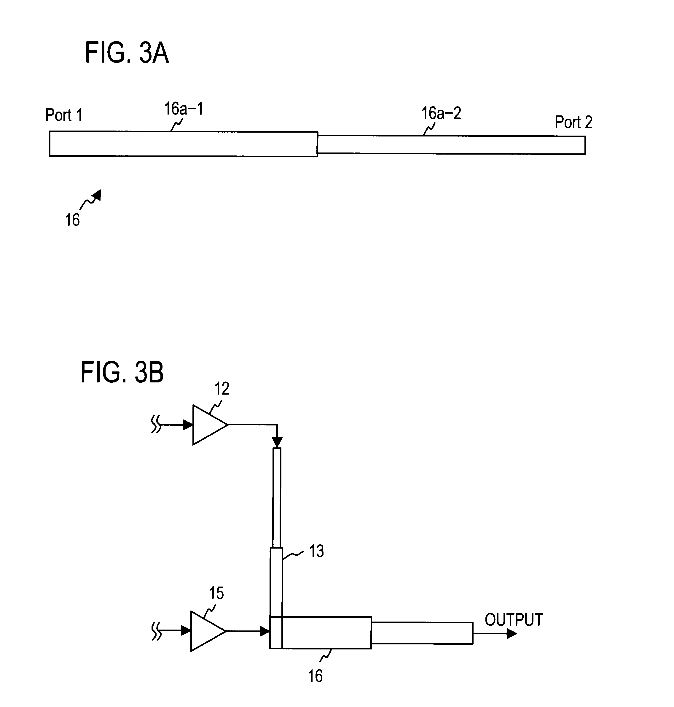
[0049]The embodiment of the multiband Doherty amplifier 10 illustrated in FIG. 1 has a divider 11 which divides an input signal into two, a carrier amplifier 12 which is connected to one output port of the divider 11 and amplifies one of the divided signals from the divider 11, a delay transmission line 14 which is connected as a delay element to the other output port of the divider 11 and causes the other divided signal to delay, a peak amplifier 15 which is connected to an output port of the delay transmission line 14 and amplifies the output signal, a multiband impedance converter 13 which is connected to an output port of the carrier amplifier 12 and performs an impedance conversion and a multiband combiner 16 which is c...


PUM


Abstract

A multiband Doherty amplifier having a configuration including a divider which divides an input signal into two, a carrier amplifier which amplifies one of the divided signals, a delay element which delays the other divided signal, a peak amplifier which amplifies the output signal of the delay element, an impedance converter which is connected to an output port of the carrier amplifier and performs predetermined impedance conversion and a combiner which combines the output signals of the peak amplifier and the impedance converter, wherein the electric length of the delay element is the same as the electric length of the impedance converter and the impedance converter has N (N≧2) cascade-connected impedance conversion transmission lines and performs substantially the same impedance conversion at each of the N frequencies.

Description

TECHNICAL FIELD[0001]The present invention relates to a high efficiency power amplifier for a transmitter, and more particularly, to a Doherty amplifier.BACKGROUND ART[0002]A Doherty amplifier configuration is known as a configuration to achieve high efficiency of a power amplifier, in which two amplification circuits of different operation classes are arranged in parallel (e.g., see Non-Patent literature 1). FIG. 10 shows a basic configuration of a conventional Doherty amplifier.[0003]As shown in FIG. 10, a conventional Doherty amplifier 100 is constructed of a divider 101 which divides an input signal into two, a carrier amplifier 102 to which one of the divided signals from the divider 101 is inputted, a ¼-wave transmission line 104 to which the other divided signal is inputted, a peak amplifier 105 to which the output signal of the ¼-wave transmission line 104 is inputted, a ¼-wave transmission line 103 to which the output signal of the carrier amplifier 102 is inputted and a co...

Claims


Application Information

Patent Timeline
Patent Type & Authority Applications(United States)
IPC IPC(8): H03F3/68
CPCH03F1/0288H03F3/602H03F2200/543H03F2200/451H03F2200/111H03F1/07
Inventor SUZUKI, YASUNORINARAHASHI, SHOICHI
Owner NTT DOCOMO INC
Why Eureka
Try Eureka