

Antenna coil to be mounted on a circuit board and antenna device
- Summary
- Abstract
- Description
- Claims
- Application Information
AI Technical Summary
Benefits of technology
Problems solved by technology
Method used
Image

Examples
first preferred embodiment
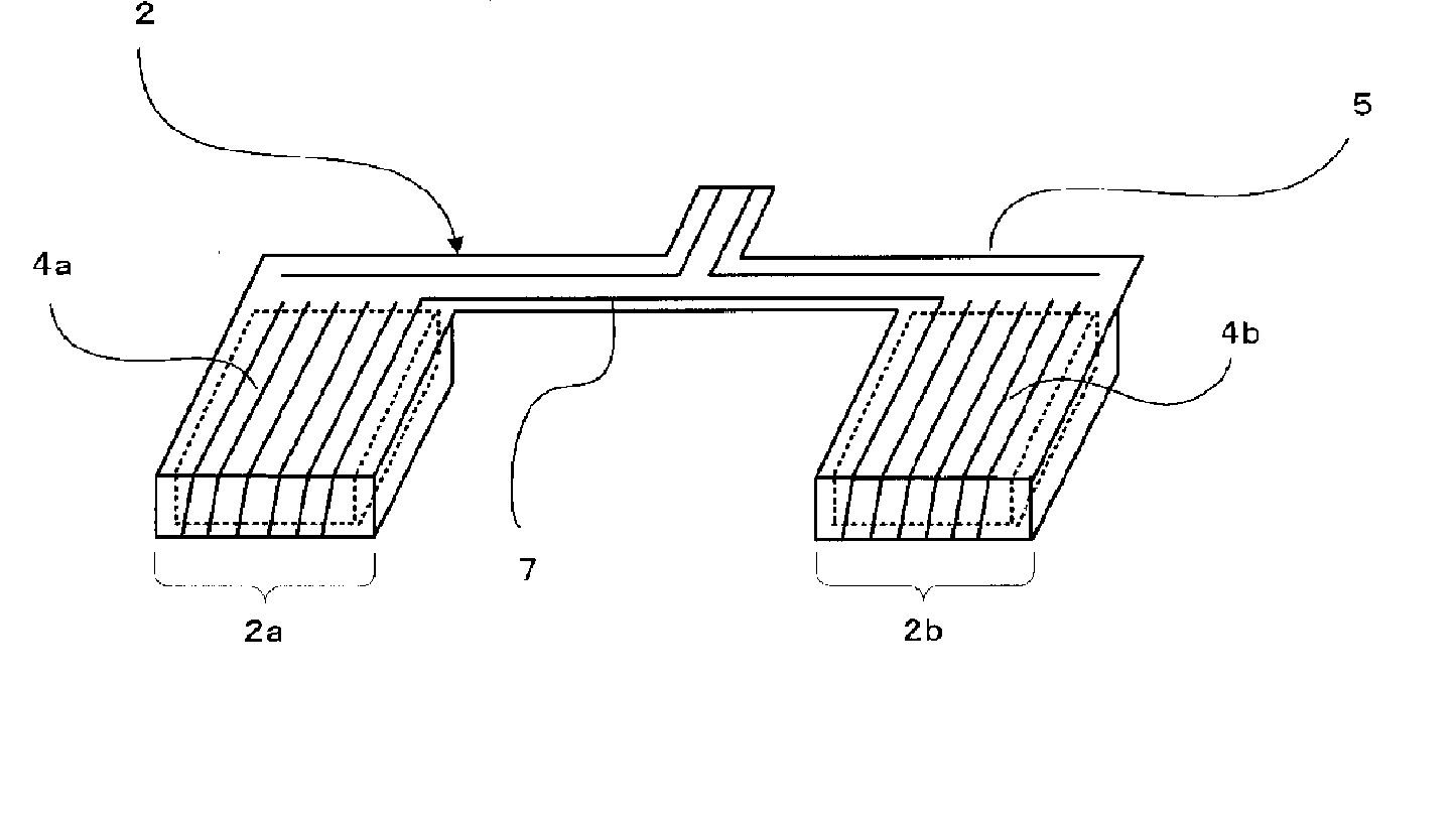
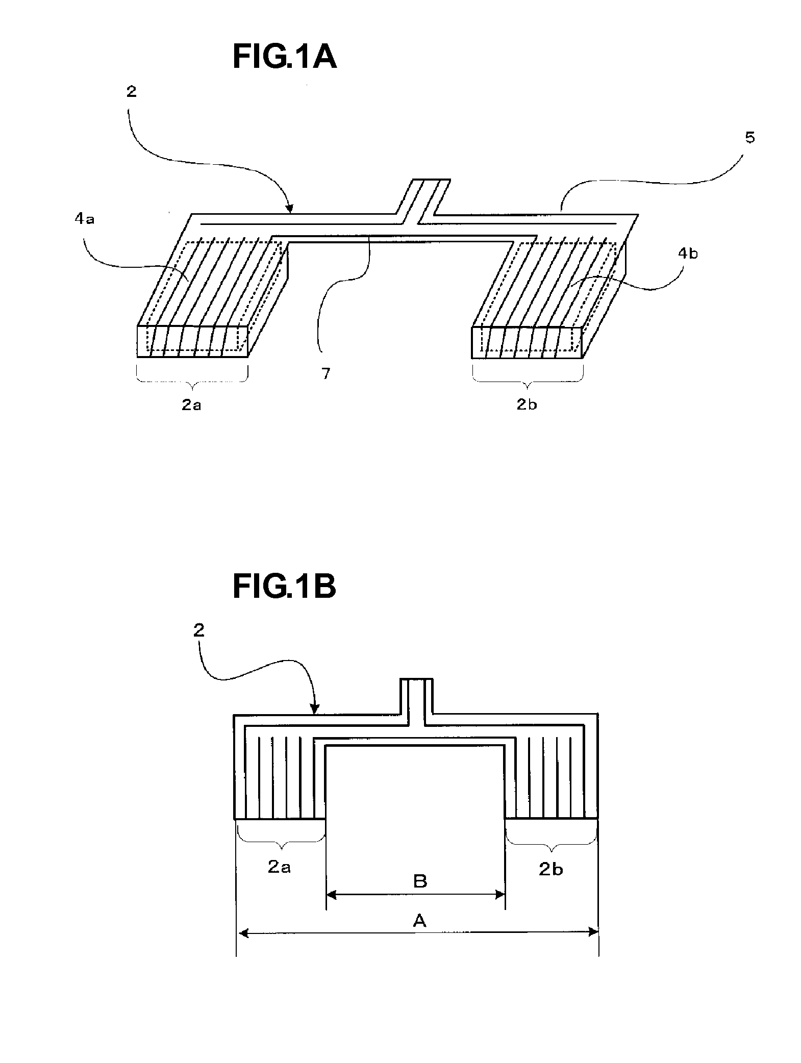
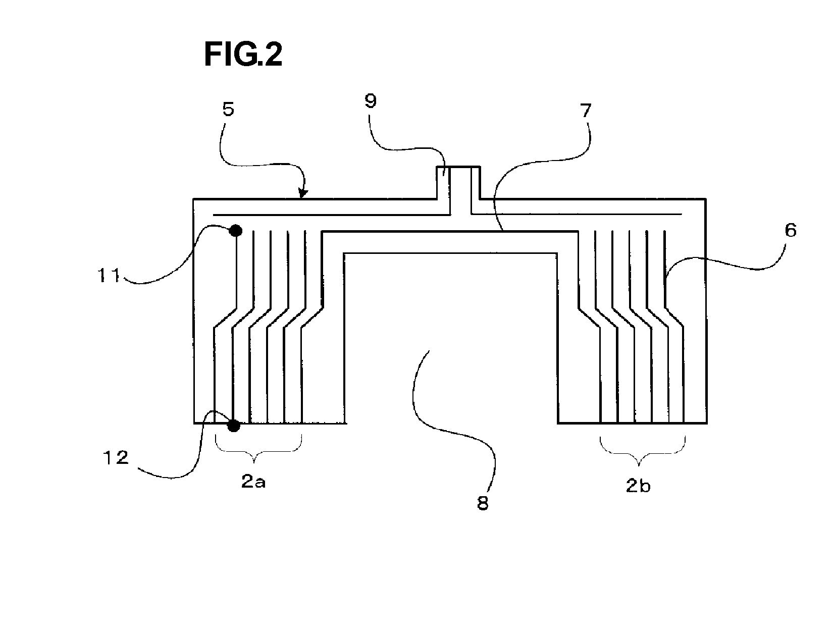
[0043] A structure of an antenna coil to be mounted on a circuit board according to a first preferred embodiment will be described with reference to FIGS. 1A, 1B and 2. FIGS. 1A and 1B are a perspective view and a plan view showing the structure of the antenna coil to be mounted on a circuit board according to the first preferred embodiment. FIG. 2 is a plan view showing a structure of a flexible board before being wound around magnetic cores.
[0044] As shown in FIGS. 1A and 1B, an antenna coil 2 according to the first preferred embodiment includes a first magnetic core 4a, a second magnetic core 4b, and one flexible board 5 wound around the first magnetic core 4a and the second magnetic core 4b. While the flexible board 5 is shown by a single line, in actuality, it has a thickness of approximately several tens of micrometers.
[0045] For example, each of the first magnetic core 4a and the second magnetic core 4b is formed of a substantially rectangular ferrite material with a princi...
second preferred embodiment
[0060] A configuration of an antenna device in which an antenna coil to be mounted on a circuit board according to a second embodiment is mounted on a circuit board will be described with reference to FIGS. 3A, 3B and 4. FIGS. 3A and 3B are a perspective view and a plan view, respectively, showing the configuration of the antenna device in which the antenna coil to be mounted on a circuit board of the second preferred embodiment is mounted. FIG. 4 is a schematic view showing a magnetic flux path formed in a state in which the antenna device shown in FIGS. 3A and 3B is held over a reader / writer for an RFID system.
[0061] As shown in FIG. 3A, an antenna coil 22 is mounted on a circuit board 21 in an antenna device 23 according to the second preferred embodiment. For example, the circuit board 21 preferably has a substantially rectangular principal surface having a length of about 90 mm and a width of about 40 mm, for example. The lateral length of the antenna coil 22 coincides with th...
third preferred embodiment
[0070] In an antenna coil to be mounted on a circuit board according to a third preferred embodiment, magnetic cores are connected to ends of a first magnetic core and a second magnetic core on both outer sides in the coil axis direction. Structures of the antenna coil that will not be described in the following examples conform to those adopted in the first preferred embodiment. However, a projection for connection to an input / output terminal is not provided.
First Example
[0071]FIG. 5 shows a structure of an antenna coil 82 in which magnetic cores 88a and 88b extending in a direction that is perpendicular or substantially perpendicular to the coil axis direction of the antenna coil 82 are respectively provided at ends of a first magnetic core 84a and a second magnetic core 84b. The connected magnetic cores 88a and 88b preferably are about 10 mm in longitudinal length, about 1.5 mm in lateral length, and about 2.3 mm in thickness, for example. The magnetic core 88a is bonded to an ...
PUM
 Abstract
Description
Claims
Application Information