Communications system transmitting/receiving using plural antennas, transmission apparatus and reception apparatus of the system

a communication system and antenna technology, applied in multiplex communication, wireless commuication services, high-level techniques, etc., can solve the problems of unmodulated transmission data, unfavorable demodulation of transmission data, and less efficient transmission control information received in the data channel. , to achieve the effect of unnecessary electric power consumption

Inactive Publication Date: 2008-01-10
FUJITSU LTD
View PDF14 Cites 29 Cited by
  • Summary
  • Abstract
  • Description
  • Claims
  • Application Information

AI Technical Summary

Benefits of technology

[0027]According to these aspects of the present invention, the number of antennas that transmit the multiplexed transmission control information in the control channel area can be determined in accordance with the propagation channel condition. Therefore, when the propagation channel is in good condition, unnecessary electric power consumption, which is caused if the multiplexed transmission control information is transmitted through plural antennas, is prevented. In addition, when the propagation channel is in poor condition, the number of antennas that transmit the control channel in which the multiplexed transmission control information is stored is increased, so that a reception rate of the transmission control information through superposed reception is improved, thereby retaining propagation quality comparable to the propagation quality realized by the multi-antenna control channel method.

Problems solved by technology

In the aforementioned 1Tx control channel transmission method, since the transmission control information of the control channels for corresponding antennas is transmitted through one control channel area for one transmission antenna, the transmission control information may be received less efficiently than the transmission data in the data channels, depending on interference from other antennas and degradation in communications channels.
In this case, the transmission data cannot be demodulated even when the transmission data in the data channel are accurately received, if the transmission control information is not accurately received.
However, this is not always a practical solution, because the transmission power for each antenna cannot be increased beyond power source capacity.
However, when the propagation channels are in a good condition, the transmission power is unduly consumed by transmitting the transmission control information through all the antennas.
In other words, in the conventional multi-antenna control channel transmission method, since the transmission control information is stored in every control channel area and transmitted through a fixed number of transmission antennas regardless of the propagation channel conditions, such transmission consumes unnecessary electric power and also interferes with other communications.
If this happens, the control channel cannot be received even when the data channel is successfully received, which results in unsuccessful demodulation of the transmission data in the data channel.

Method used


Image

  • Communications system transmitting/receiving using plural antennas, transmission apparatus and reception apparatus of the system
  • Communications system transmitting/receiving using plural antennas, transmission apparatus and reception apparatus of the system
  • Communications system transmitting/receiving using plural antennas, transmission apparatus and reception apparatus of the system

Examples


Embodiment Construction

[0034]Referring to the accompanying drawings, embodiments of the present invention will be described.

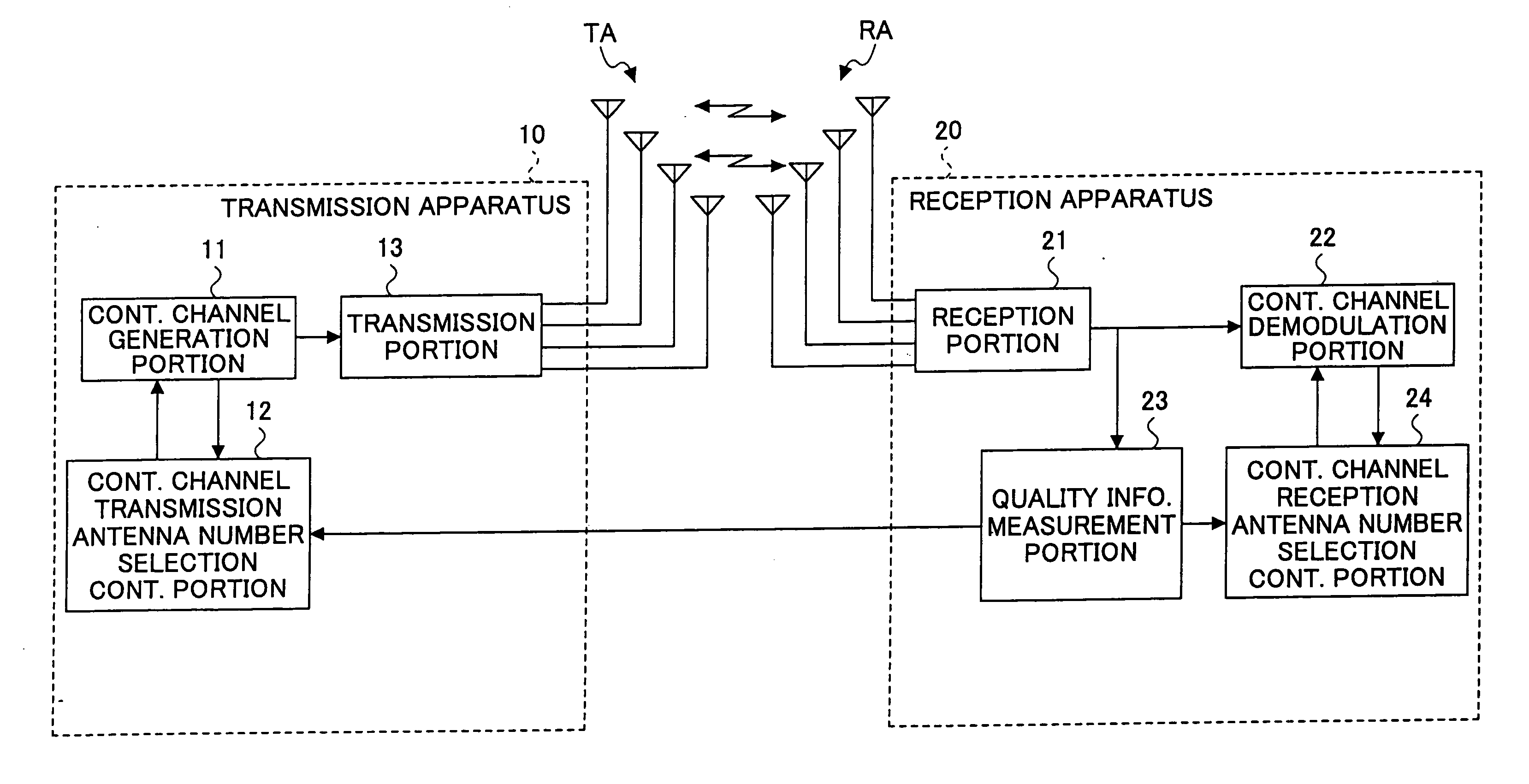
[0035]FIG. 3 illustrates function blocks of a transmission apparatus and a reception apparatus of a communications system according to an embodiment of the present invention. In addition, FIG. 4 is a flowchart illustrating an operational sequence of the transmission apparatus according to the embodiment of the present invention. FIG. 5 illustrates another flowchart illustrating an operational sequence of the reception apparatus according to the embodiment of the present invention.

[0036]In a transmission apparatus 10, an antenna number selection control portion 12 configured to select the number of control channel transmission antennas recognizes a current condition of a propagation channel based on transmission quality information transmitted from a quality information measurement portion 23 of a reception apparatus 20 so as to select the number of the transmission antennas for use i...


PUM


Abstract

In a disclosed transmission apparatus, a control channel transmission antenna number selection control portion selects the number of transmission antennas that transmit a control channel in accordance with transmission quality information received from a quality information measurement portion of a reception apparatus. In addition, a control channel generation portion generates multiplexed transmission control information obtained by multiplexing multiple pieces of transmission control information for corresponding radio signals and storing the generated multiplexed transmission control information in a control channel area of at least one of transmission frames for transmitting the information. The number of the transmission antennas that transmit the control channel is determined to be one, the maximum number of the transmission antennas, or any number between one and the maximum number.

Description

BACKGROUND OF THE INVENTION[0001]1. Field of the Invention[0002]The present invention relates to a communications system that transmits / receives through one or more antennas in accordance with a MIMO (Multiple-Input Multiple-Output) method or the like, a transmission apparatus, and a reception apparatus for the communications system. Specifically, the present invention relates to a communications system, a transmission apparatus, and a reception apparatus that are capable of effectively transmitting a control channel.[0003]2. Description of the Related Art[0004]Currently, the MIMO method is drawing much attention as a technology that enables high capacity (high speed) data communications by effectively utilizing a frequency band. The MIMO method uses a reception apparatus having plural antennas and a transmission apparatus having plural antennas. The MIMO method transmits independent data streams from the plural antennas of the transmission apparatus and the data streams are receive...

Claims


Application Information

Patent Timeline
Patent Type & Authority Applications(United States)
IPC IPC(8): H04Q7/06H04J99/00
CPCH04B7/063H04B7/0691H04B7/0632Y02D30/70
Inventor SATOU, HIDEYORIKONTA, SHINJI
Owner FUJITSU LTD
Why Eureka
Try Eureka