Lock apparatus for a safety needle assembly

a technology for locking apparatus and safety needles, which is applied in the field of safety syringes, can solve the problems of inability to reuse safety syringes, insufficient design of locking mechanisms, and contaminated needle risks for users, and achieves the effects of convenient assemblage, low manufacturing cost, and durable construction

Inactive Publication Date: 2008-01-10
DEVON SAFETY PRODS
View PDF8 Cites 28 Cited by
  • Summary
  • Abstract
  • Description
  • Claims
  • Application Information

AI Technical Summary

Benefits of technology

[0015] It is another object of this invention to provide a safety lock mechanism preventing a used needle from being reused which can be incorporated into a safety needle assembly.
[0028] It is still another object of this invention to provide a locking apparatus for use in a safety needle assembly which is durable in construction, inexpensive of manufacture, facile in assemblage, and simple and effective in use.

Problems solved by technology

While such a configuration provides an excellent protection for health care workers from accidental needle sticks, the mechanism does not prevent intravenous drug users from overriding the safety features and re-using the needle for illicit drug purposes, exposing the user to risks associated with contaminated needles.
Such locking mechanisms are not designed to prevent a determined drug user from overriding the locking mechanism to permit the plunger to be retracted from the barrel in order to re-use the needle.
Once used, the safety syringe cannot be re-used.
Such multiple needle sizes for each barrel size requires many different parts and greatly increases the manufacturing complexity in providing safety needles for use by the health care industry.
The needle locking mechanism depicted in the aforementioned U.S. Pat. No. 6,626,863, is somewhat complex and difficult to manufacture and assemble.
Each manipulation of the needle presents an independent risk for an accidental stick into the health care practitioner.

Method used


Image

  • Lock apparatus for a safety needle assembly
  • Lock apparatus for a safety needle assembly
  • Lock apparatus for a safety needle assembly

Examples


Embodiment Construction

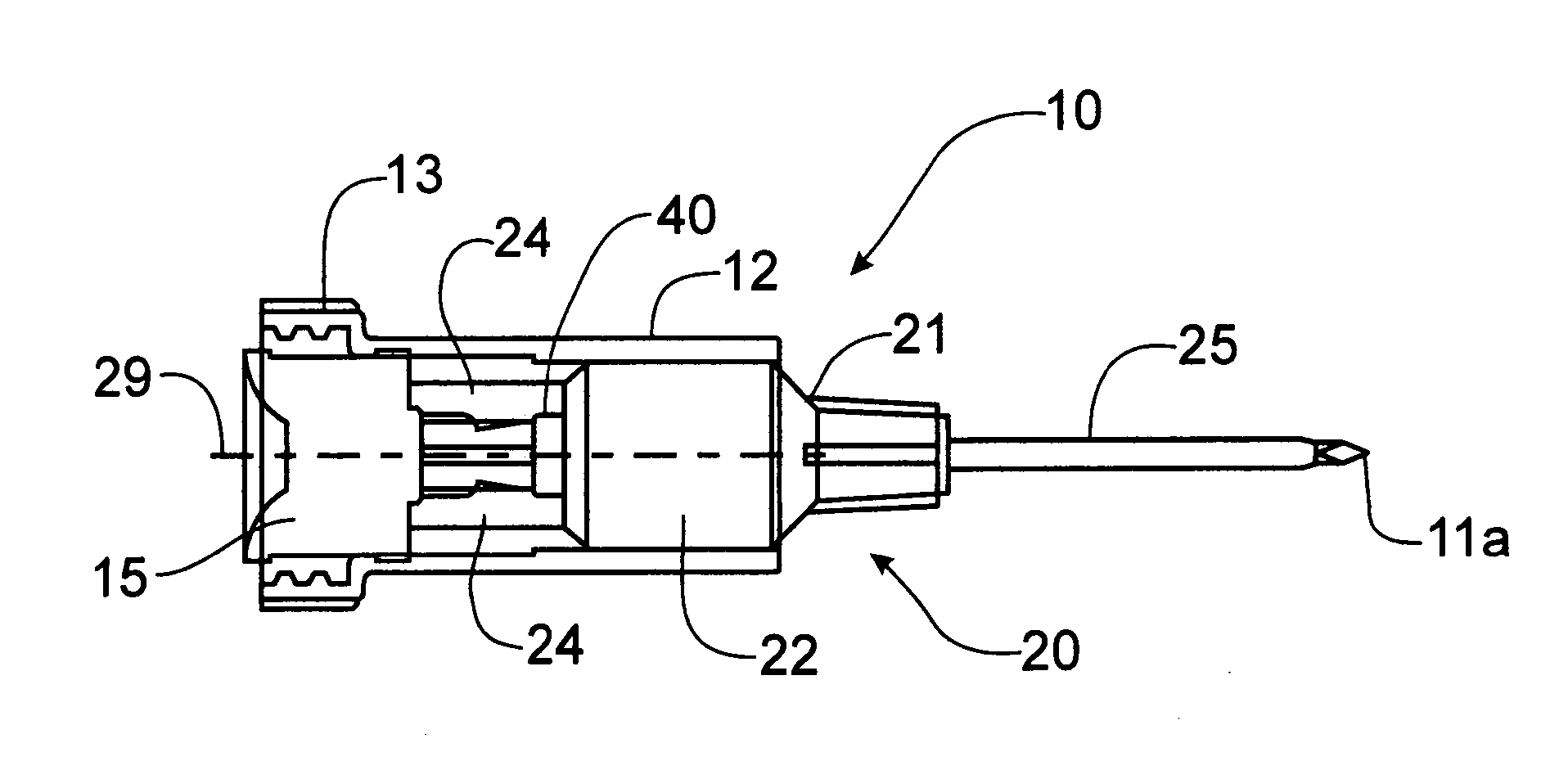
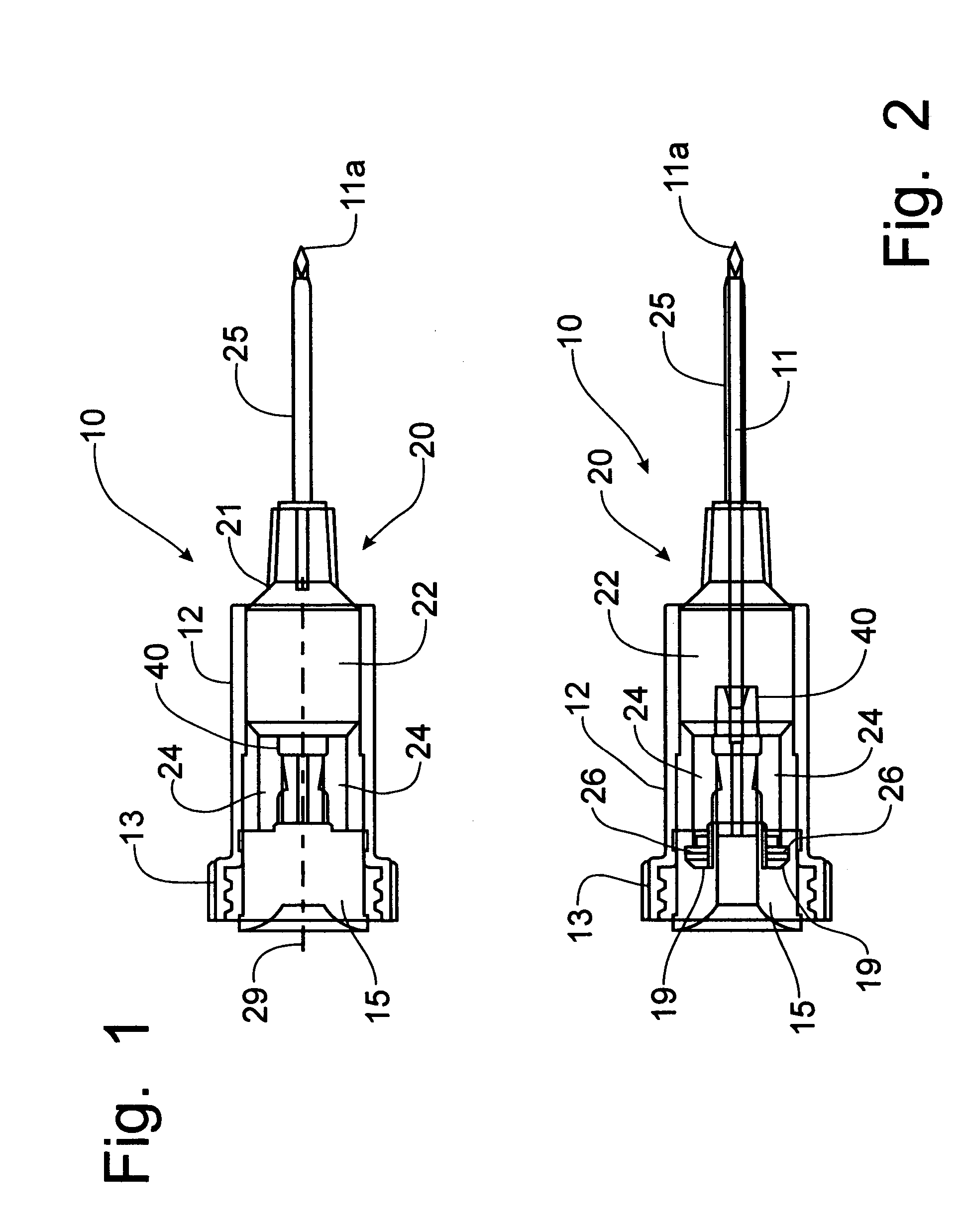
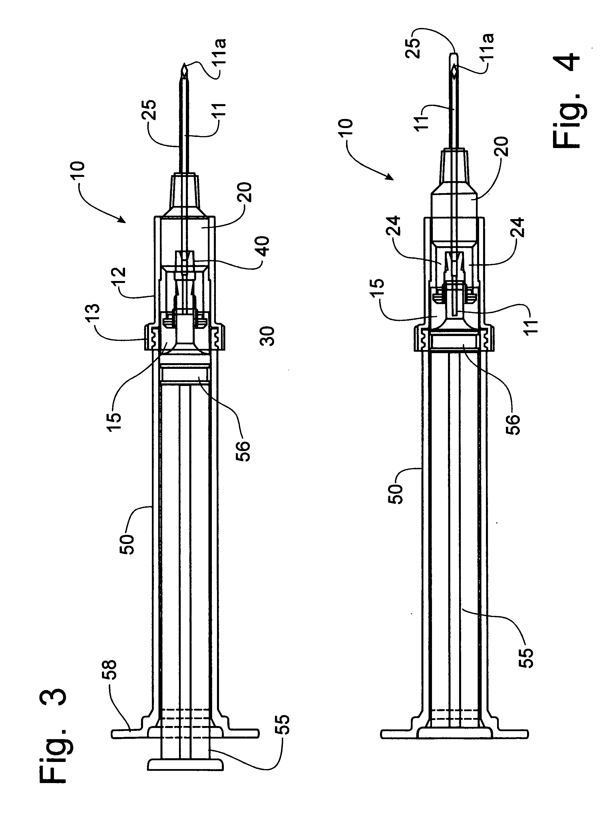
[0056] Referring to the drawings, the components of a safety needle assembly incorporating the principles of the instant invention can best be seen. The safety needle assembly 10 includes an outer housing 12 including a collar 13 threaded for quick connection to the receptor on a suitably configured syringe barrel. The diaphragm 15 is mounted within the housing 12 to provide a fluid-tight seal against the housing 12 and has an actuator side 16, facing the syringe barrel 50, and a needle side 17 from which the needle 11 projects. The needle 11 is received through the diaphragm 15, passing through a bore 44 in a central needle support 40 and projecting outwardly therefrom in an axial manner with respect to the housing 12.

[0057] The safety needle assembly 10 further includes an actuator 20 which includes a sheath head 21 through which the needle 11 passes and is extendible therefrom. The sheath head 21 includes a body portion 22 and a pair of axially extending legs 24 that project tow...


PUM


Abstract

A safety needle assembly has a rigid housing that encloses a locking mechanism cooperable with actuator that slides over the tip of the needle to prevent accidental sticks after the needle has been used. The locking mechanism operates to place into interference two members, one of which is fixed relative to the outer housing, while the other is formed on the actuator that is slidably mounted in the housing for movement in response to the syringe plunger reaching the end movement at the bottom of the syringe barrel to move from an exposed position into a covered position. In one embodiment, the actuator includes a pair of axially extending legs having cam members formed thereon to engage a bridge member spanning diametrically across the housing. A safety cap is formed with ribs around the mounting end to prevent the safety cap from rolling across a planar surface.

Description

CROSS-REFERENCE TO RELATED APPLICATIONS [0001] This application claims domestic priority on U.S. Provisional Patent Application Ser. No. 60 / 688,938, filed Jun. 9, 2005, and on U.S. Provisional Patent Application Ser. No. 60 / 717,085, filed Sep. 14, 2005, the contents of both provisional applications being incorporated herein by reference.FIELD OF THE INVENTION [0002] The present invention relates generally to safety syringes of the type to cover the point of the needle after use to prevent accidental sticks with a contaminated needle, and, more particularly, to a lock apparatus that is suitable for use in a safety needle assembly that can be used on different syringe barrels. BACKGROUND OF THE INVENTION [0003] Safety syringes are known in the art, such as depicted in U.S. Pat. No. 5,720,727, issued to Gary Alexander on Feb. 24, 1998, the sheath is advanced by operation of the plunger. While such a configuration provides an excellent protection for health care workers from accidental ...

Claims


Application Information

Patent Timeline
Patent Type & Authority Applications(United States)
IPC IPC(8): A61M5/31
CPCA61M2005/3265A61M5/326
Inventor BERLER, BARRY B.
Owner DEVON SAFETY PRODS
Why Eureka
Try Eureka