Intramedullary nail

a technology of intramedullary nail and nail, which is applied in the field of intramedullary nail, can solve the problems of inability to use in relatively linear tubular bones, and achieve the effect of slight curvature of the intramedullary nail

Active Publication Date: 2008-01-10
SYNTHES USA
View PDF20 Cites 25 Cited by
  • Summary
  • Abstract
  • Description
  • Claims
  • Application Information

AI Technical Summary

Benefits of technology

[0021] Due to the formation of one or both end parts as straight sections, an advantage can be attained that the curvature of the intramedullary nail is slight. As a result, the intramedullary nail is particularly suitable for straight, tubular bones.

Problems solved by technology

A disadvantage of this known intramedullary nail that it is not suitable for use in relatively linear, tubular bones, especially the tibia.

Method used


Image

  • Intramedullary nail
  • Intramedullary nail

Examples


Embodiment Construction

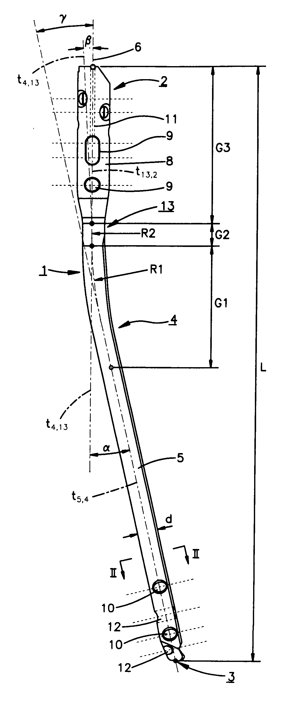
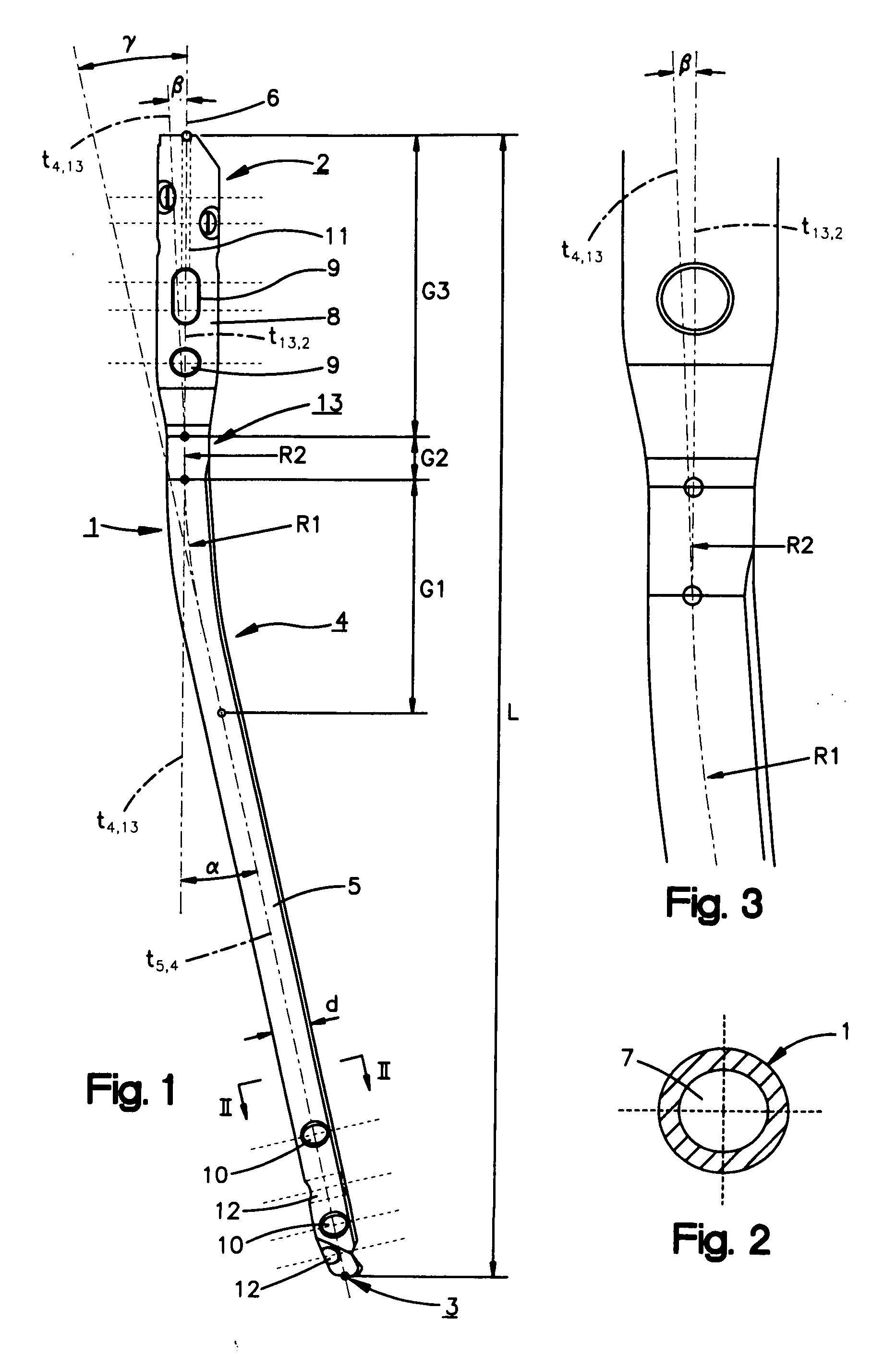
[0037] The intramedullary nail 1, shown in FIGS. 1 to 3, may comprise a central axis 6, a proximal end part 2, a distal end part 3 that is suitable for introduction into the intramedullary space and two curved sections 4; 13 disposed axially one behind the other. The total length of the intramedullary nail “L” ranges from about 200 mm to about 500 mm. Axially, the proximal end part 2 adjoins the second, curved section 13 and is constructed as a straight, proximal section 8 of length G3. Length G3 may be less than or equal to the total length L of the intramedullary nail and preferably ranges between about ⅙L to about ⅓L. The distal end part 3 may be constructed as a straight, distal section 5 with a length “l” ranging from about 0.20L to about 0.55L, and preferably from about 0.25L to about 0.50L. The first curved section 4 may have a length G1 that is less than or equal to L, and preferably ranges from about 0.2L to about 0.4L. The first curved section may have a radius of curvatur...


PUM


Abstract

An intramedullary nail, particular for use with a tibia, may have a proximal end part, a distal end part adapted to be introduced into a medullary space, and a central section. The central section includes a first curved section having a first length with a first radius of curvature, and a second curved section having a second length shorter than the first length and a second radius of curvature smaller than the first radius of curvature. The second radius of curvature may be less than the first radius of curvature. The intramedullary nail also includes a central axis. Tangents at two end points of the central section, including the first and second curved sections, enclose an angle gamma between about 9° and about 12°. The intramedullary nail may have a total length ranging from 200 to 500 mm.

Description

CROSS REFERENCE TO RELATED APPLICATION [0001] This application is a continuation of International Patent Application No. PCT / CH2004 / 000758, filed Dec. 31, 2004, the entire contents of which is expressly incorporated herein by reference.TECHNICAL FIELD [0002] The invention relates to an intramedullary nail, particularly for use in the tibia. BACKGROUND OF THE INVENTION [0003] U.S. Pat. No. 6,020,506 to GOSNEY describes a generic intramedullary nail. The intramedullary nail has a proximal end part which can be pressed on, and a distal end part. The proximal end and the distal end are at an angle relative to one another by means of several curved segments which are disposed between the end parts. In addition, the proximal end part is bent at right angles so that a relatively large angle is formed between the tangents to the central axes at the axial ends. A disadvantage of this known intramedullary nail that it is not suitable for use in relatively linear, tubular bones, especially the...

Claims


Application Information

Patent Timeline
Patent Type & Authority Applications(United States)
IPC IPC(8): A61B17/72
CPCA61B17/72A61B17/8635A61B17/7283A61B17/56A61B17/58
Inventor SCHLIENGER, ANDREBUETTLER, MARKUSFRIGG, ROBERT
Owner SYNTHES USA
Why Eureka
Try Eureka