
Chain lock

a technology of chain lock and coupling surface, which is applied in the direction of chain elements, driving chains, chain fastenings, etc., can solve the problems of reducing the available coupling surface, having a disadvantageous effect on tensile stress and durability, and achieving significant durability. , the effect of small curvatur

Active Publication Date: 2006-04-11
J D THEILE
View PDF11 Cites 9 Cited by
  • Summary
  • Abstract
  • Description
  • Claims
  • Application Information

AI Technical Summary

Benefits of technology

"The invention is a chain lock that uses a straight or only slightly curved coupling surface segment to increase durability. This design features a coupling surface segment that runs crosswise to the joining direction of the two lock parts, which is connected by curved transition segments. By using this design, the chain lock can absorb transverse forces and is more durable than previous lock designs. The width of the coupling surface segment is adapted to the size of the chain lock and the radius of the coupling surface transition segments. The locking stays can also have an undercut projection to absorb transverse forces."

Problems solved by technology

For this reason, it would have been assumed, at first, that a reduction in the available coupling surface would have a disadvantageous effect on the tensile stress and the durability.

Method used


Image

  • Chain lock
  • Chain lock
  • Chain lock

Examples


Embodiment Construction

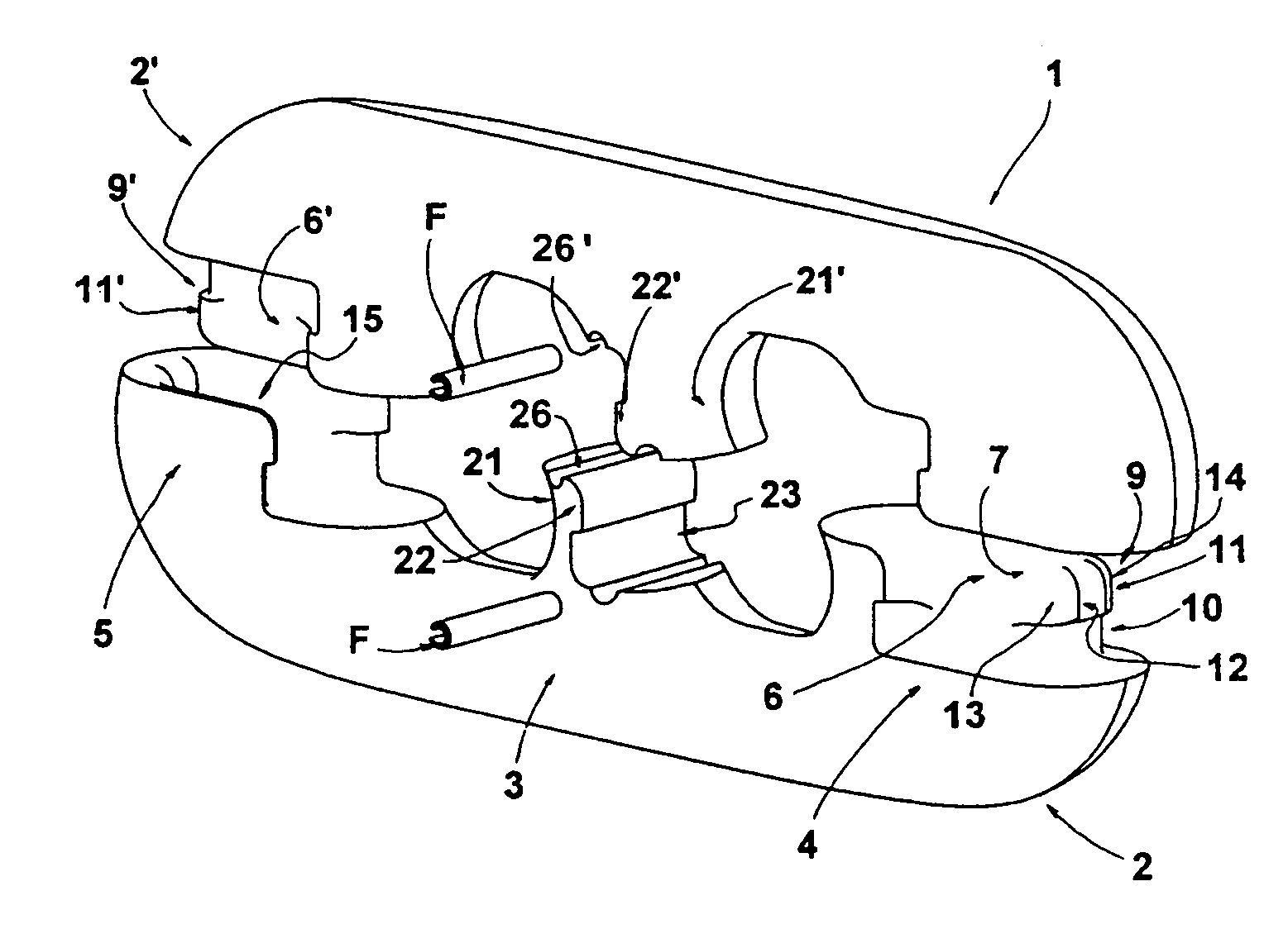
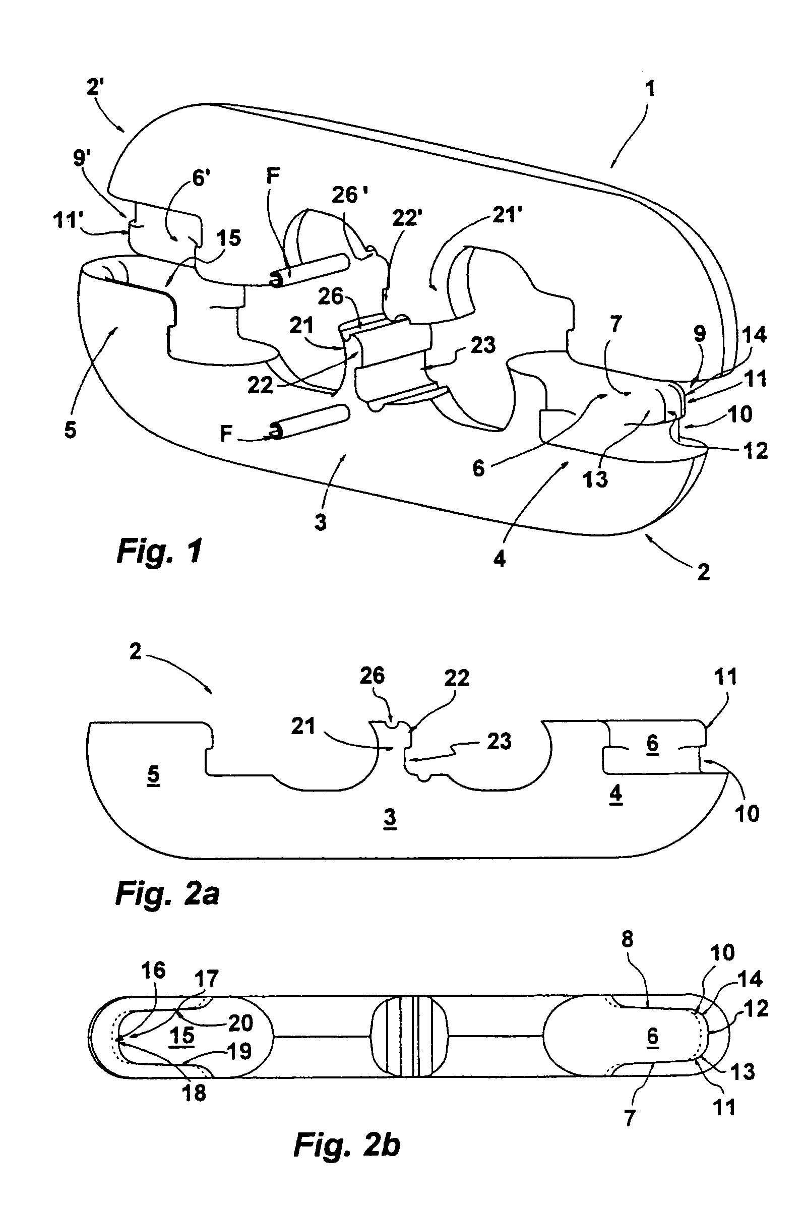
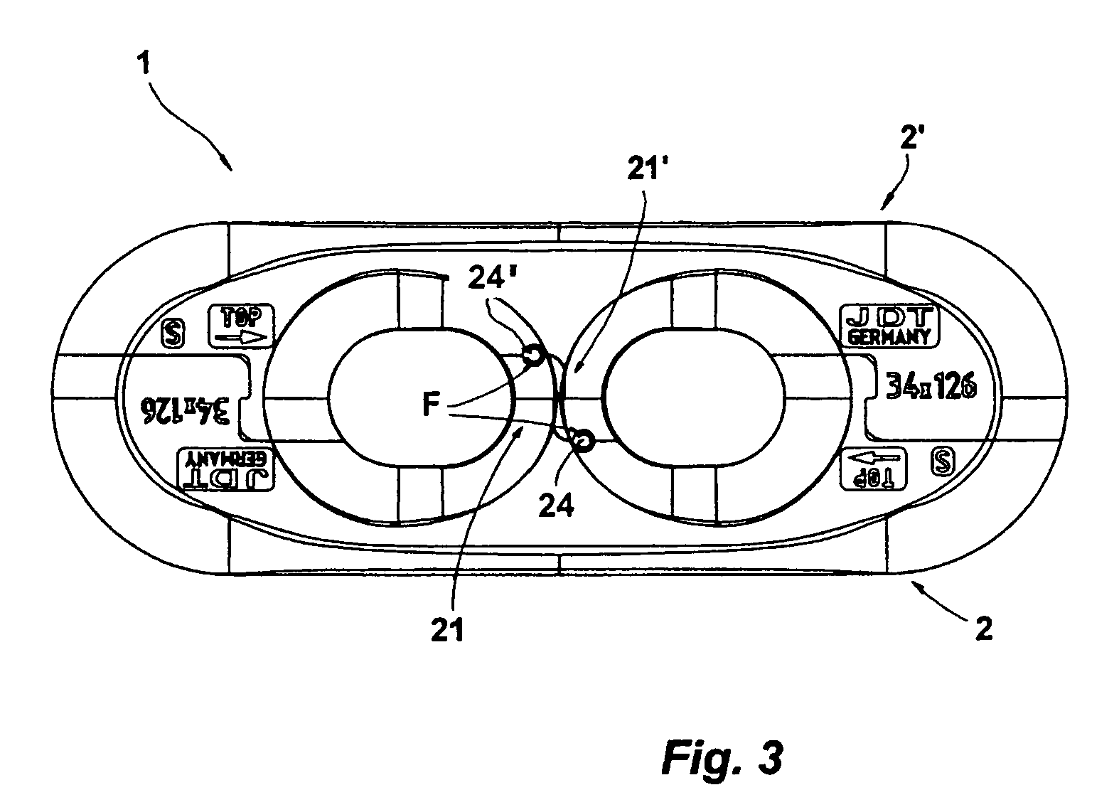
[0016]Referring now in detail to the drawings, there is shown a chain lock 1 for a high-strength steel chain, which consists of two lock parts 2, 2′. Lock parts 2, 2′ are structured identically with regard to their essential characteristics, which are described below, and are disposed with a rotational symmetry in the joining direction, relative to one another, in FIG. 1, to form the chain lock. In the following, the lock part 2 will be described in greater detail at first; the lock part 2′ has a corresponding structure.

[0017]Lock part 2 has a longitudinal stay 3, followed by an arc segment 4, 5 at both ends, in each instance. Arc segments 4, 5 have coupling elements with which lock part 2 can be connected with lock part 2′. The coupling elements of arc segments 4, 5 are configured to be complementary to one another. Arc piece 4, as a coupling element, bears a locking stay 6, the longitudinal expanse of which follows the longitudinal expanse of lock part 2. The locking stay is forme...


PUM


Abstract

A chain lock for high-strength steel chains has two lock parts that are the same and can be joined together in a rotation-symmetry arrangement with one another, in the longitudinal direction. Each lock part has a longitudinal stay having arc segments that follow it at both ends. There are two coupling elements that are configured complementary to one another and are assigned to the two arc segments of each lock part. One of the elements is configured as a locking stay that follows the longitudinal extension of the lock part, and the other element is configured as a stay accommodation. The locking stay of the one lock part engages in the stay accommodation of the other lock part and rests against the complementary coupling surface of the stay accommodation with its coupling surface formed by the face end in the joining direction. The coupling surfaces comprise a coupling surface segment having a defined width, which has no curvature or only an insignificant curvature pointing in the joining direction.

Description

CROSS-REFERENCE TO RELATED APPLICATION[0001]Applicants claim priority under 35 U.S.C. §119 of German Application No. 10 2004 028 901.8 filed Jun. 15, 2004.BACKGROUND OF THE INVENTION[0002]1. Field of the Invention[0003]The invention relates to a chain lock for high-strength steel chains, the lock having two lock parts that are the same and can be joined together in a rotation-symmetry arrangement with one another, in the longitudinal direction. There is a longitudinal stay having arc segments that follow it at both ends. One of two coupling elements that are configured complementary to one another is assigned to the two arc segments of each lock part. One of these elements is configured as a locking stay that follows the longitudinal extension of the lock part, and the other element is configured as a stay accommodation. The locking stay of the one lock part that engages in the stay accommodation of the other lock part rests against the complementary coupling surface of the stay acc...

Claims


Application Information

Patent Timeline
Patent Type & Authority Patents(United States)
IPC IPC(8): F16G15/04B21L11/00F16G15/00F16G15/02F16G15/12
CPCF16G15/02F16G15/00
Inventor BENECKE, RAINERBERGHOFF, JURGENWIRTZ, THORSTEN
Owner J D THEILE
Learn More