
Bearing structure for a reciprocating shaft in a reciprocating saw

a reciprocating saw and bearing structure technology, applied in the direction of power driven reciprocating saws, manufacturing tools, cutlery, etc., can solve the problems of unwieldy, difficult to manually move the saw blade back and forth, and difficulty in manual sawing of materials,

Inactive Publication Date: 2008-01-17
LAGALY MICHAEL ANTHONY +4
View PDF1 Cites 26 Cited by
  • Summary
  • Abstract
  • Description
  • Claims
  • Application Information

AI Technical Summary

Benefits of technology

"The invention is a combination of a reciprocating shaft and bearing for a reciprocating saw. It includes a housing, a fixed pin, and a reciprocating shaft assembly with a blade holder for holding a saw blade. The assembly moves in a reciprocating motion relative to the fixed pin and is supported as a bearing during this motion. The technical effect of this invention is to provide a reliable and efficient mechanism for the reciprocating motion of a saw blade."

Problems solved by technology

Manually sawing these materials would be a difficult and time consuming undertaking.
Further, many applications require a saw to be used in a confined area where it would be even more difficult to move a saw blade manually back and forth.
This configuration causes the saw to be longer than necessary, which can render impossible, or at best complicate, some cuts to be performed in a limited space.
A long saw is also generally awkward to use and unwieldy, and is difficult to store when not in use.
Furthermore, in some known reciprocating saws, the housing for the saw assembly is unnecessarily complicated and expensive.
First, the exterior surface of the gear box can be expensive to manufacture.
Manufacturing a smooth gear box can increase the cost of the saw.
Also, since the gear box can become very hot during prolonged use of the saw, an insulating covering is sometimes necessary to insulate a user's hands from the heat of the gear box.
Applying an insulating covering to the gearbox, while potentially eliminating the cost of producing a smooth gear box, is nonetheless still an added expense.
This can add to the cost of manufacturing the saw.
Furthermore, reciprocating saws create vibration.
While such a configuration may diminish undesirable vibration, it does not provide a configuration as compact and convenient as possible.

Method used


Image

  • Bearing structure for a reciprocating shaft in a reciprocating saw
  • Bearing structure for a reciprocating shaft in a reciprocating saw
  • Bearing structure for a reciprocating shaft in a reciprocating saw

Examples


Embodiment Construction

[0022] The preferred embodiments of the invention pertain to a hand-held reciprocating saw. Although the invention is described in connection with a particularly preferred arrangement of components, various alternative configurations are also possible. Modifications to the preferred embodiments will be readily apparent to those skilled in the art without departing from the spirit and scope of the invention. Thus, the following description of the preferred embodiments are illustrative only. For convenience, similar elements are designated throughout the drawing figures with the same reference numerals.

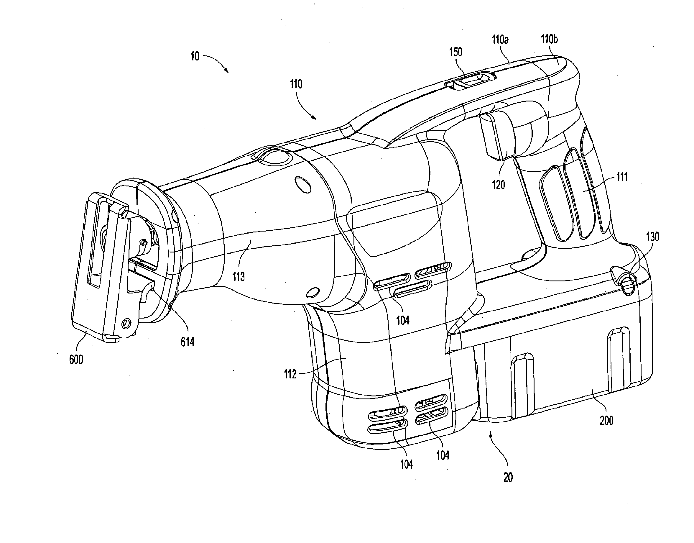
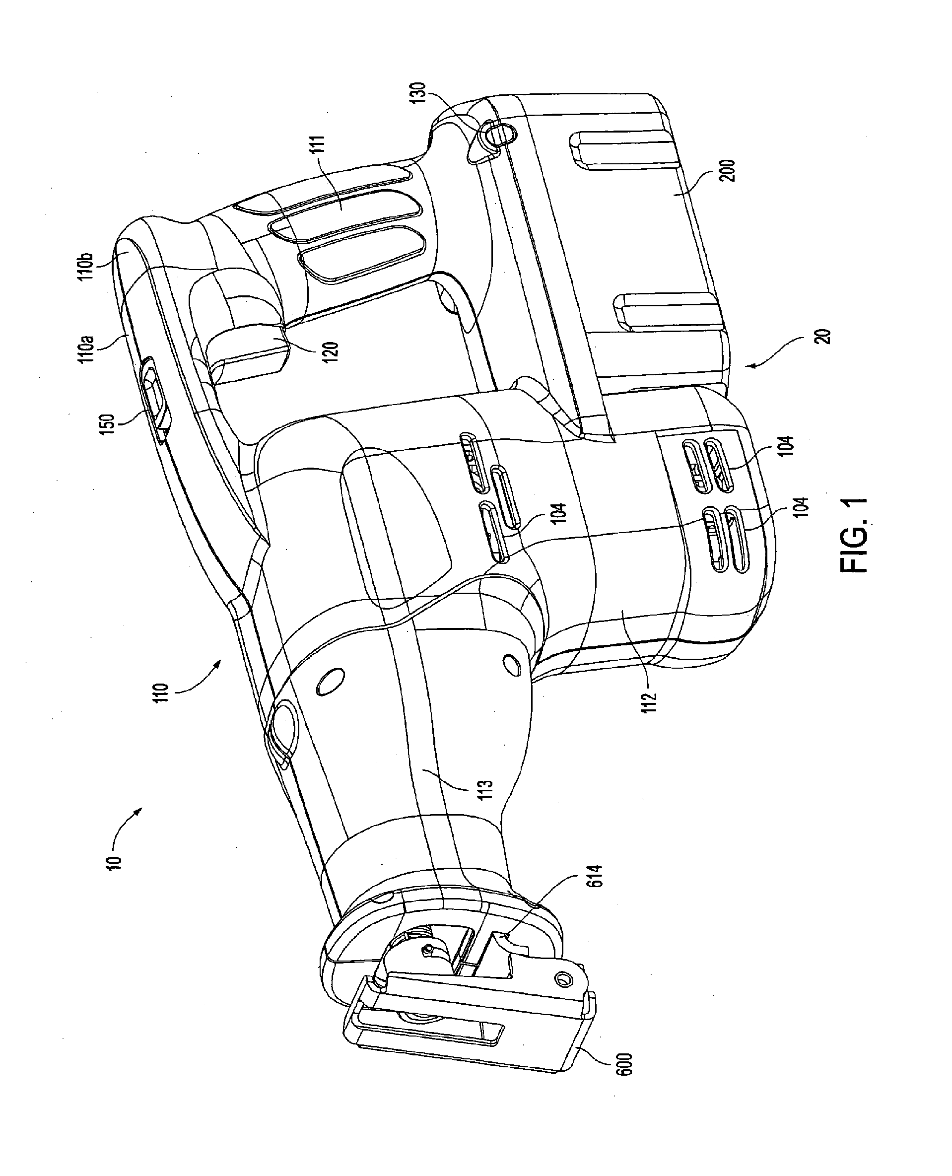
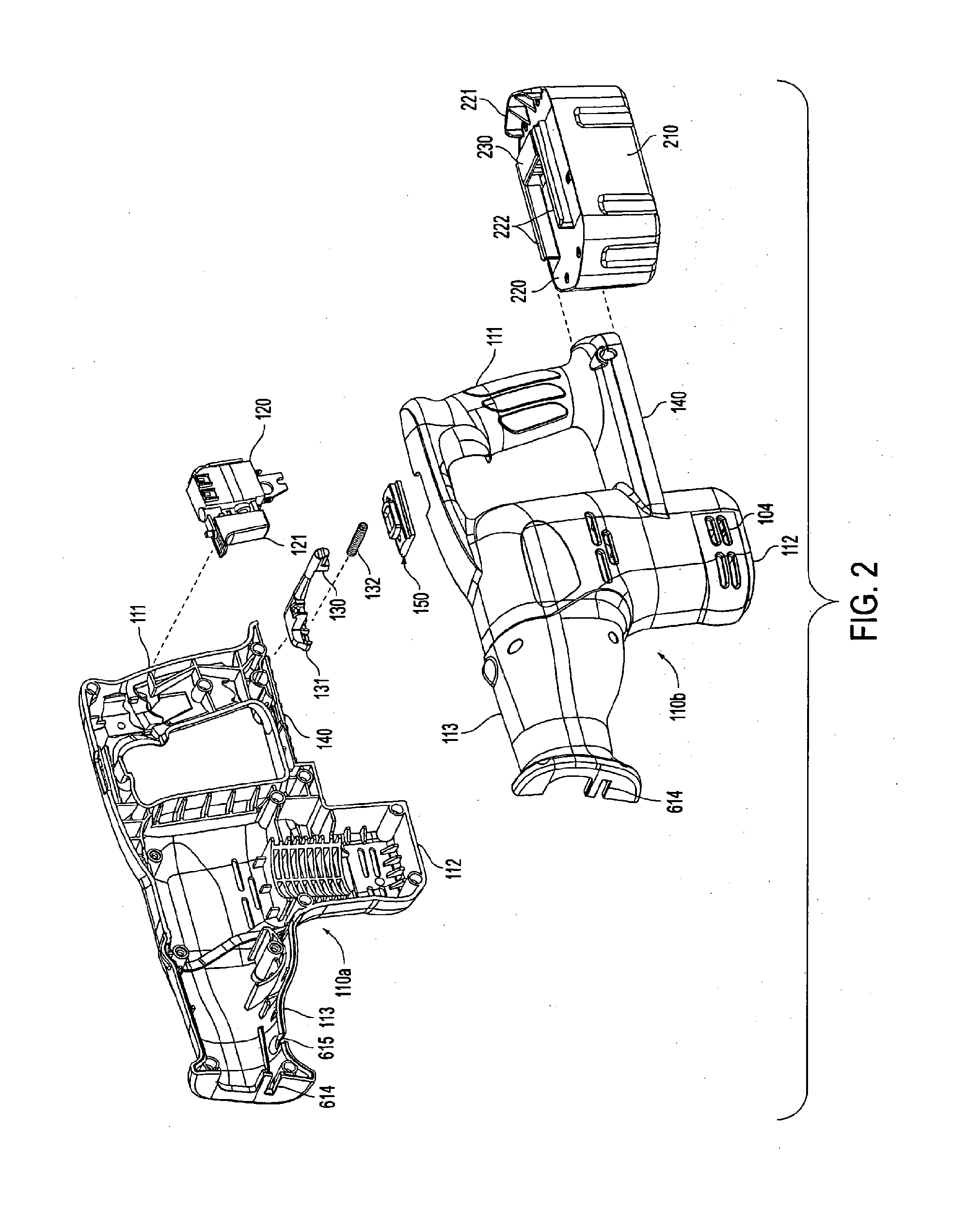
[0023] With reference to FIGS. 1 and 2, the reciprocating saw 10 includes a two-piece housing 110 comprising two mating clam-shell halves 110a and 110b. The two-piece housing 110 may be injection molded plastic in which each half preferably includes a plurality of matching bosses and bores for receiving fasteners (not shown) which hold together the two mating clam-shell halves 110a and...


PUM

PropertyMeasurementUnit
angleaaaaaaaaaa
poweraaaaaaaaaa
radius of curvatureaaaaaaaaaa

Abstract

A reciprocating shaft assembly in a reciprocating saw moves in a reciprocal motion and drives a saw blade via a blade holder. At least one bore is formed in an end of the reciprocating shaft assembly opposite the blade holder. A pin fixed to the saw passes through the bore and acts as a bearing to support the reciprocating shaft assembly in its reciprocating motion.

Description

CROSS-RELATED APPLICATIONS [0001] This application is a divisional of, claims priority to, and incorporates by reference in its entirety, the following U.S. patent application Ser. No. 10 / 871,592, entitled “RECIPROCATING COUNTERWEIGHT STRUCTURE FOR A RECIPROCATING SAW,” filed Jun. 21, 2004, which is a continuation of U.S. patent application Ser. No. 10 / 364,472, entitled “BEARING STRUCTURE FOR A RECIPROCATING SHAFT IN A RECIPROCATING SAW,” filed Feb. 12, 2003 (issued as U.S. Pat. No. 6,810,589), which is a divisional of U.S. patent application Ser. No. 09 / 627,780, entitled “RECIPROCATING SAW HAVING COMPACT CONFIGURATION AND INDEPENDENT STABILITY,” filed Jul. 28, 2000 (issued as U.S. Pat. No. 6,568,089), which is a continuation-in-part of U.S. patent application Ser. No. 29 / 123,137, entitled “BATTERY POWERED RECIPROCATING SAW,” filed May 10, 2000 (abandoned), which is a continuation-in-part of U.S. patent application Ser. No. 29 / 105,953, entitled “BATTERY POWERED RECIPROCATING SAW,” f...

Claims


Application Information

Patent Timeline
Patent Type & Authority Applications(United States)
IPC IPC(8): B27B19/02B23D49/16B23D51/16
CPCB23D49/162B23D51/02B23D51/16F16F15/28Y10T74/2183Y10T74/18208Y10T24/1903Y10T74/18248Y10S30/01
Inventor LAGALY, MICHAEL ANTHONYMOOTY, THOMAS ARNOLDNICHOLS, JAMES PIERCE JR.CLOWERS, EARL ROGERPOPIK, MATTHEW GEORGE
Owner LAGALY MICHAEL ANTHONY
Learn More