

Charging station for portable electronic instruments
a portable electronic instrument and charging station technology, applied in the direction of mobile unit charging stations, transportation and packaging, and battery arrangement, etc., can solve the problem of unsightly looping or unsightly laying of cords on counters or floors
- Summary
- Abstract
- Description
- Claims
- Application Information
AI Technical Summary
Problems solved by technology
Method used
Image

Examples
second embodiment
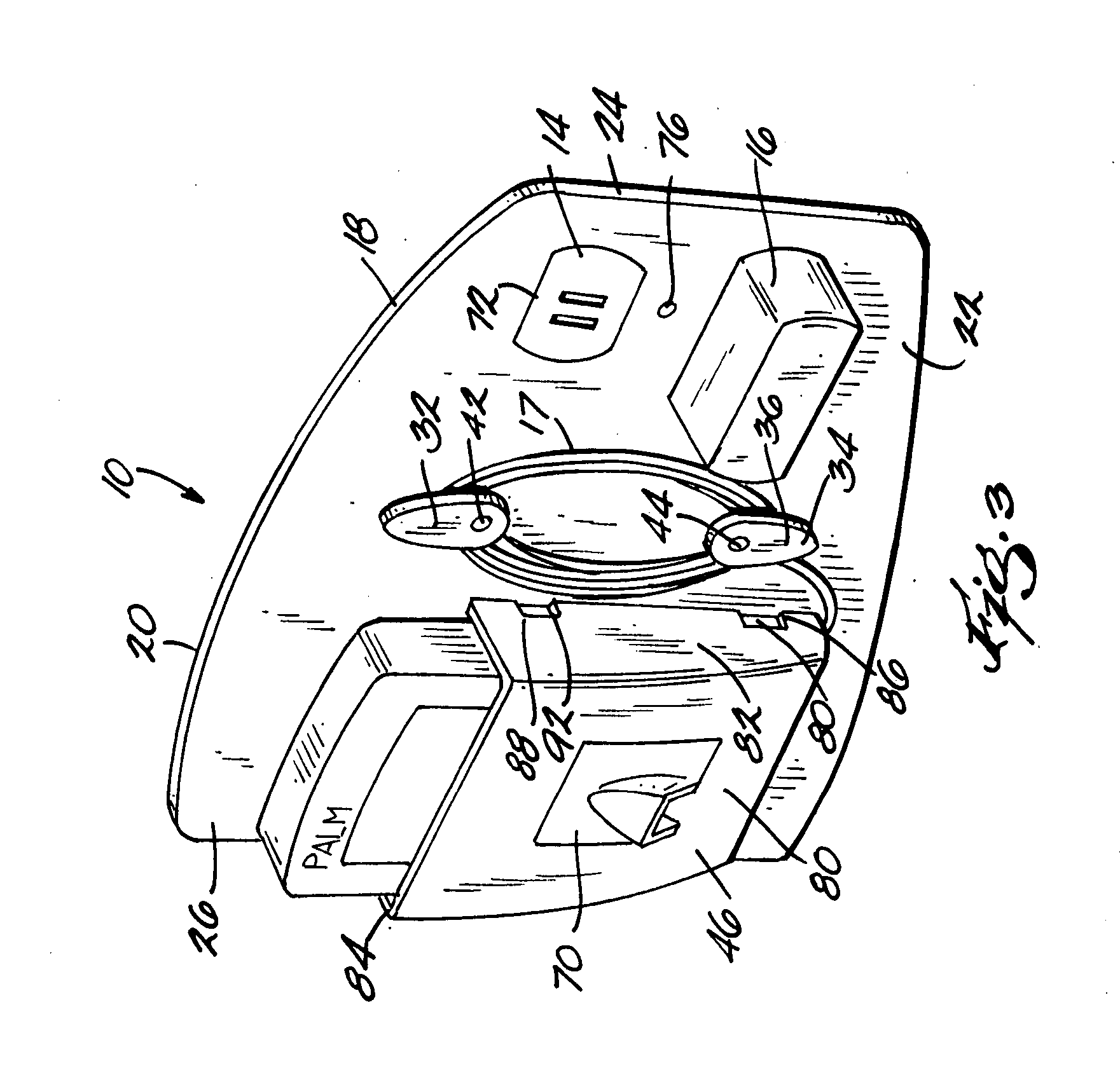
[0028]FIG. 3 shows the charging station 10. In this embodiment, the base is elongated to also act as a cover for the electrical outlet 14. In this embodiment, there is no need for an aperture in the base 18 to allow the cord to go from the outlet 14 to the interior of the charging station, since the base of the charging station also acts as the cover for the outlet. The base has a pair of major apertures 72 and 74, only one of which is shown since the transformer 16 hides the second aperture. The base 18 also includes a minor aperture 76 that accepts a screw for holding the base 18 to the electrical outlet 14 and accordingly, the wall 15 (not shown in this view). In this embodiment, both hooks 36 and 42 are provided with means to allow the wings 34 and 44 to rotate about a longitudinal access extended through the respective stems 36 and 42. It is to be understood that either one or both of the hooks 34 and 42 could be stationary as shown in bottom hook of FIG. 1.
[0029] In any event,...
third embodiment
[0030]FIG. 4 shows the invention. In this embodiment, the base acts as a cover for the electrical outlet similar to that shown in FIG. 3. Specifically, the base has a pair of major apertures 72 and 74 (not shown, hidden by the transformer 16) and a minor aperture 76 again for receiving a screw for holding the base 18 onto the electrical outlet and accordingly the wall. The mounting can be supplemented with a hook and loop fastener such as Velcro®.
[0031] In the FIG. 4 embodiment however, there is a pair of hooks and a pair of pockets for charging two PEI's simultaneously. The pockets are also shown having clips 86 and 88 and associated apertures 90 and 92 for mounting the respective pockets on the base. As can be appreciated, the pockets may be different and associated with specific sizes of PEI's.
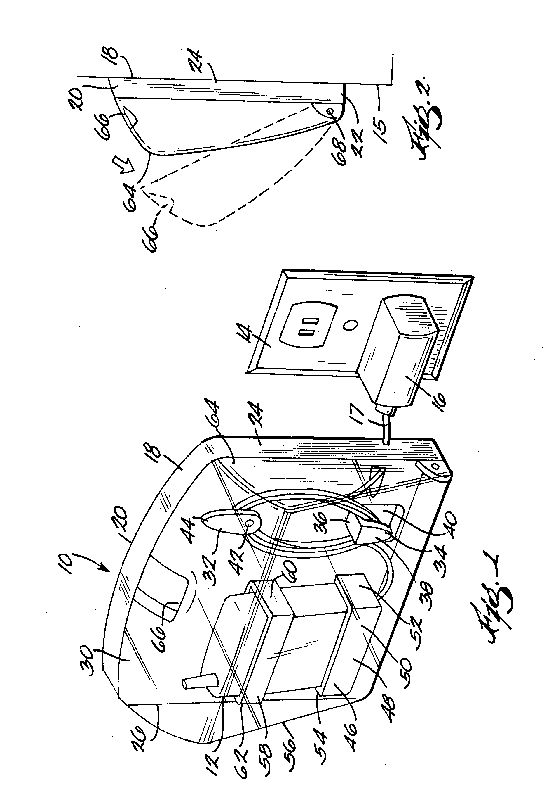
[0032] As seen in FIG. 5, the base 18 may have a varying cross section in thickness. The portion near the center for mounting on the electrical outlet 14 may be thin so that the transforme...
PUM
 Abstract
Description
Claims
Application Information