
Design and method for keeping electrical contacts closed during short circuits

a technology of electrical contacts and short circuits, applied in the direction of circuit-breaking switches, contact mechanisms, dynamo-electric relays, etc., can solve the problems of arcing and heating, contact damage, contact arcing and heating, and high risk of circuit control pod damag

Inactive Publication Date: 2008-01-17
SIEMENS IND INC
View PDF9 Cites 16 Cited by
  • Summary
  • Abstract
  • Description
  • Claims
  • Application Information

AI Technical Summary

Benefits of technology

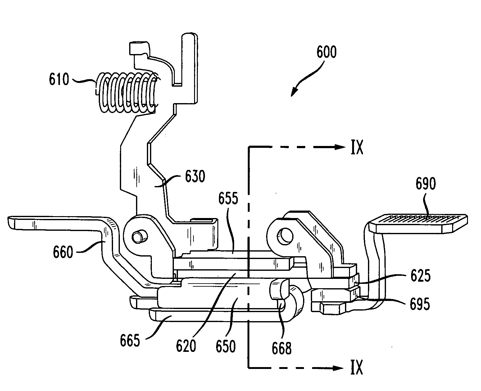
[0012]The assembly may include a braided wire electrically connecting the moveable and fixed conductors. The braided wire connection may be the only braided wire connection of the contact assembly. The fixed conductor may include a tab extending from the fixed conductor in a direction away from a plane of the fixed conductor, the braided wire being connected to the tab, whereby parasitic loss in the magnetic field of the moveable and fixed conducting surfaces due to a secondary magnetic field is reduced.
[0019]The method may also comprise the step of flowing the electric current through a braided wire electrically connecting the moveable and fixed conductors. The braided wire connection may be the only braided wire connection of the contact assembly. The current may additionally be flowed through a tab extending from the fixed conductor away from a plane of the fixed conductor, the braided wire being connected to the tab, whereby parasitic loss in the magnetic field of the moveable and fixed conducting surfaces due to a secondary magnetic field is reduced.

Problems solved by technology

Those secondary contacts are intended to be switched more often than the primary pair of contacts, but do not have the robustness to maintain their intended function if exposed to the arc and heat associated with a short circuit.
Without the incorporation of specific design features, electromagnetic forces tend to open those secondary contacts under large current loads before the primary contacts interrupt the circuit, causing arcing and heating and potentially damaging the contacts.
Under those conditions, there is a high risk that the circuit control pod would be damaged.

Method used


Image

  • Design and method for keeping electrical contacts closed during short circuits
  • Design and method for keeping electrical contacts closed during short circuits
  • Design and method for keeping electrical contacts closed during short circuits

Examples


Embodiment Construction

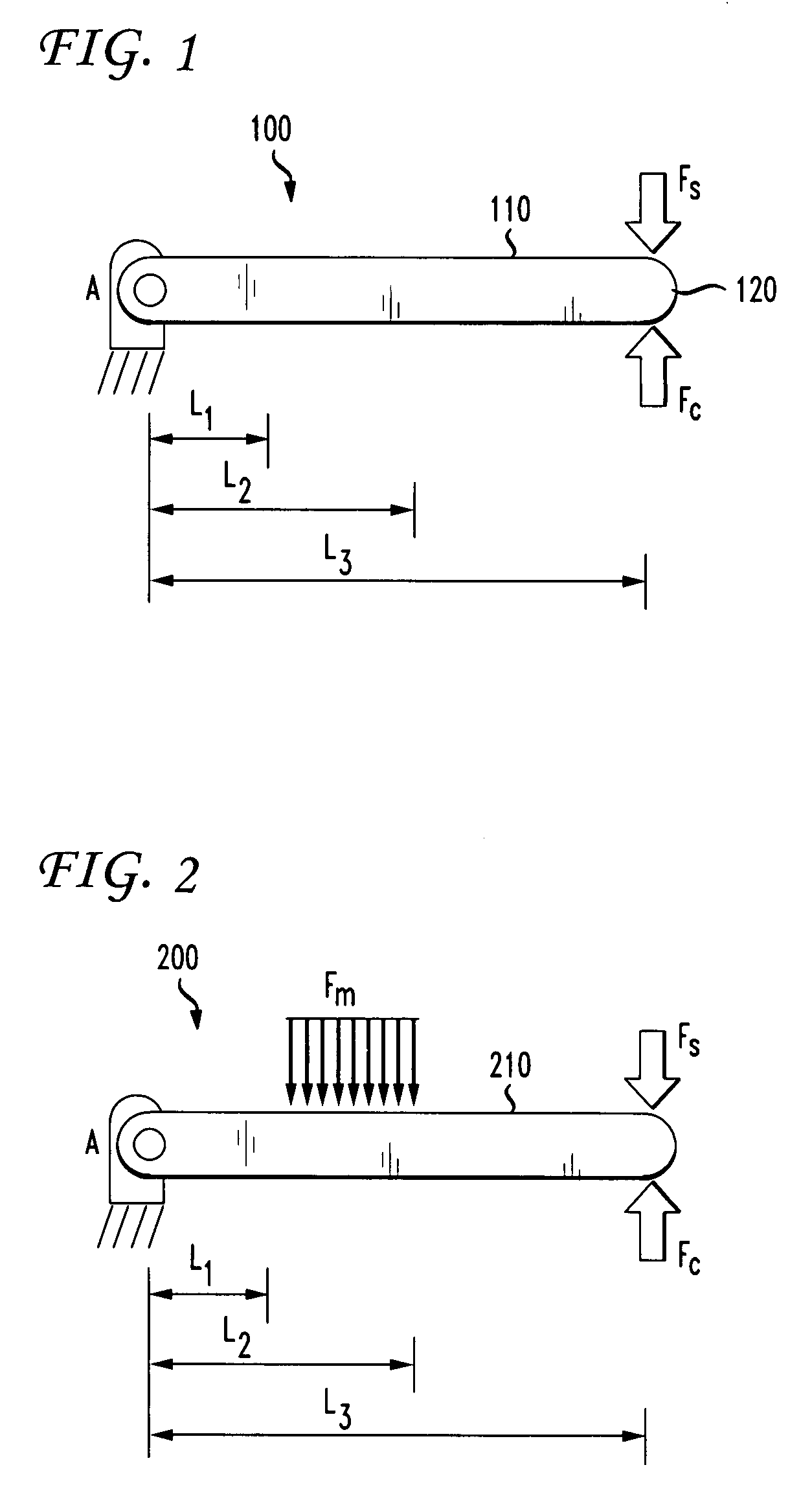
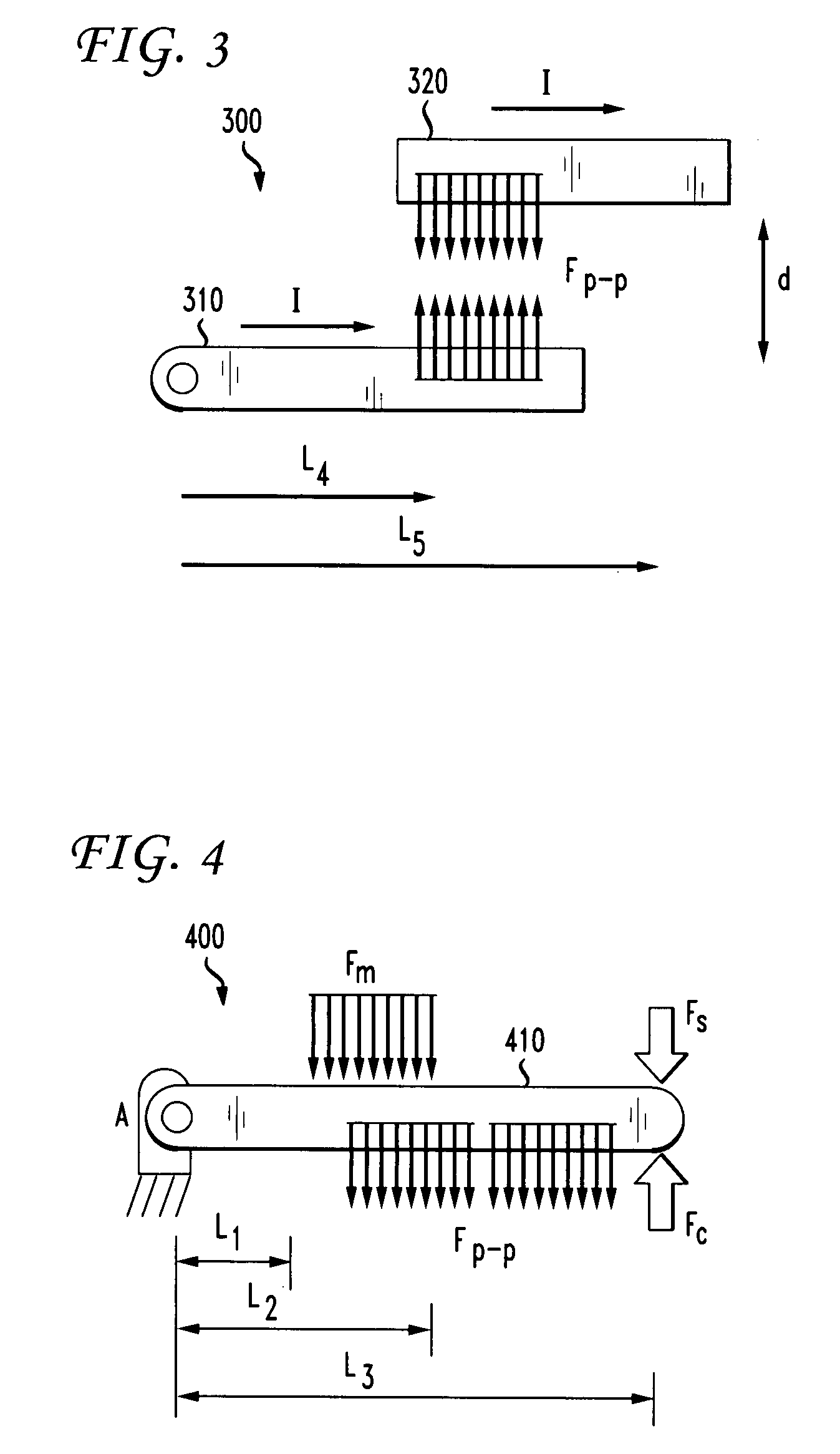
[0037]The present invention relates to a method and apparatus for keeping a pair of contacts closed as they conduct current in a wide range of levels. The invention incorporates features that act independently of the current level, proportionally to the current level, and proportionally to the square of the current level. Those three levels of control allow a designer greater flexibility when creating a system that protects a pair of contacts from opening unexpectedly. The contact assembly of the invention is particularly useful in remote controlled devices where one pair of contacts is not intended to interrupt a short-circuit event. Specific examples of such applications include circuit breakers, relays, contactors, and breaker accessories that are used for lighting control.

[0038]The present invention incorporates a “blow closed” loop that prevents the separation of contacts in the contact assembly during short circuits. The contact assembly of the present invention utilizes a gro...


PUM


Abstract

An electrical contact assembly resists blow-open under conditions of increased current flow. The contact assembly includes parallel conducting surfaces on fixed and moveable conductors that generate forces biasing the contacts together under current flow conditions. The assembly also includes a magnetic armature and yoke that exert a magnetic force to resist movement of the contacts toward the open position. Current flowing through both the fixed and moveable conductors contribute to the magnetic force. A spring may additionally bias the contacts to the closed position. The contact assembly may be used in remote-controlled circuit breaker applications.

Description

CROSS REFERENCE TO RELATED APPLICATIONS[0001]This application claims the benefit of priority from U.S. Provisional Patent Application Ser. No. 60 / 830,533 entitled “Design and Method for Keeping Electrical Contacts Closed During Short Circuits,” filed on Jul. 13, 2006, the contents of which are hereby incorporated by reference herein in their entirety.FIELD OF THE INVENTION[0002]The present invention relates generally to an improved contact assembly and circuit breaker assembly, and more particularly, to a remote controlled circuit breaker assembly having remote controlled contacts that resist blowing open under increased load conditions.BACKGROUND OF THE INVENTION[0003]There has been an increasing demand for remotely controllable circuit breaker assemblies that can reciprocate between an open circuit and a closed circuit in response to a remotely generated command. One advantageous application for such circuit breaker assemblies is in control panelboards that are used for automated ...

Claims


Application Information

Patent Timeline
IPC IPC(8): H01H89/06H01H1/00H01H1/54H01H75/00
CPCH01H89/10H01H89/06H01H1/54H01H73/00H01H75/00H01H77/00
Inventor DEBOER, JOHNMCCOY, BRIAN TIMOTHY
Owner SIEMENS IND INC
Learn More