Three-Dimensional Imaging System Using Optical Pulses, Non-Linear Optical Mixers And Holographic Calibration

a three-dimensional imaging and optical pulse technology, applied in the field of three-dimensional imaging, can solve the problems of complex implantation of light emitters and their associated active control electronics, the need for a high refresh rate of voxels for real-time displays, and the difficulty of maintaining operation and construction of high-definition displays

Active Publication Date: 2008-01-17
STEVENS INSTITUTE OF TECHNOLOGY
View PDF23 Cites 168 Cited by
  • Summary
  • Abstract
  • Description
  • Claims
  • Application Information

AI Technical Summary

Benefits of technology

[0019]Further features and advantages of the invention will appear more clearly on a reading of the following detailed description of several exemplary embodiments of the invention.

Problems solved by technology

The problem in both holographic display classes is the need for a high refresh rate of the voxels for real time displays.
The rotating light source approach has problems connecting a large number of light sources to a moving screen and therefore their high definition displays are difficult to construct and maintain in operation.
Implementations utilizing light sources on the moving screen such as the light emitting diodes (LEDs) of the Berlin '973 Patent result in complex implantations of light emitters and their associated active control electronics which are also included with the rotating screen.
While this approach has the advantage of high simultaneous transfer of image data to moving screen, its moving mechanism becomes mechanically more complicated as the size and thus the forces for moving the display increases.
Furthermore, the accuracy of positioning of the projections in specific voxels decreases as the size of the display increases because of the increasing forces on the rotating screen and because the pointing error of the projection beams increases as display size increases.
The calibration of three-dimensional image acquisition equipment which includes optical recorders, especially for those configurations using multiple cameras, is a very time consuming process, as they require calibration for all the points in the target space.
Current calibration techniques using real objects moved through all the calibration points of the target space do not provide continuous real time calibration since optical properties of the optical recorders change with zoom adjustments, wear, or mechanical deformation under acceleration.
Such three-dimensional image scanners are not able to capture both shape and color.

Method used


Image

  • Three-Dimensional Imaging System Using Optical Pulses, Non-Linear Optical Mixers And Holographic Calibration
  • Three-Dimensional Imaging System Using Optical Pulses, Non-Linear Optical Mixers And Holographic Calibration
  • Three-Dimensional Imaging System Using Optical Pulses, Non-Linear Optical Mixers And Holographic Calibration

Examples


Embodiment Construction

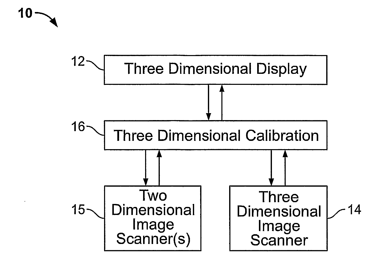
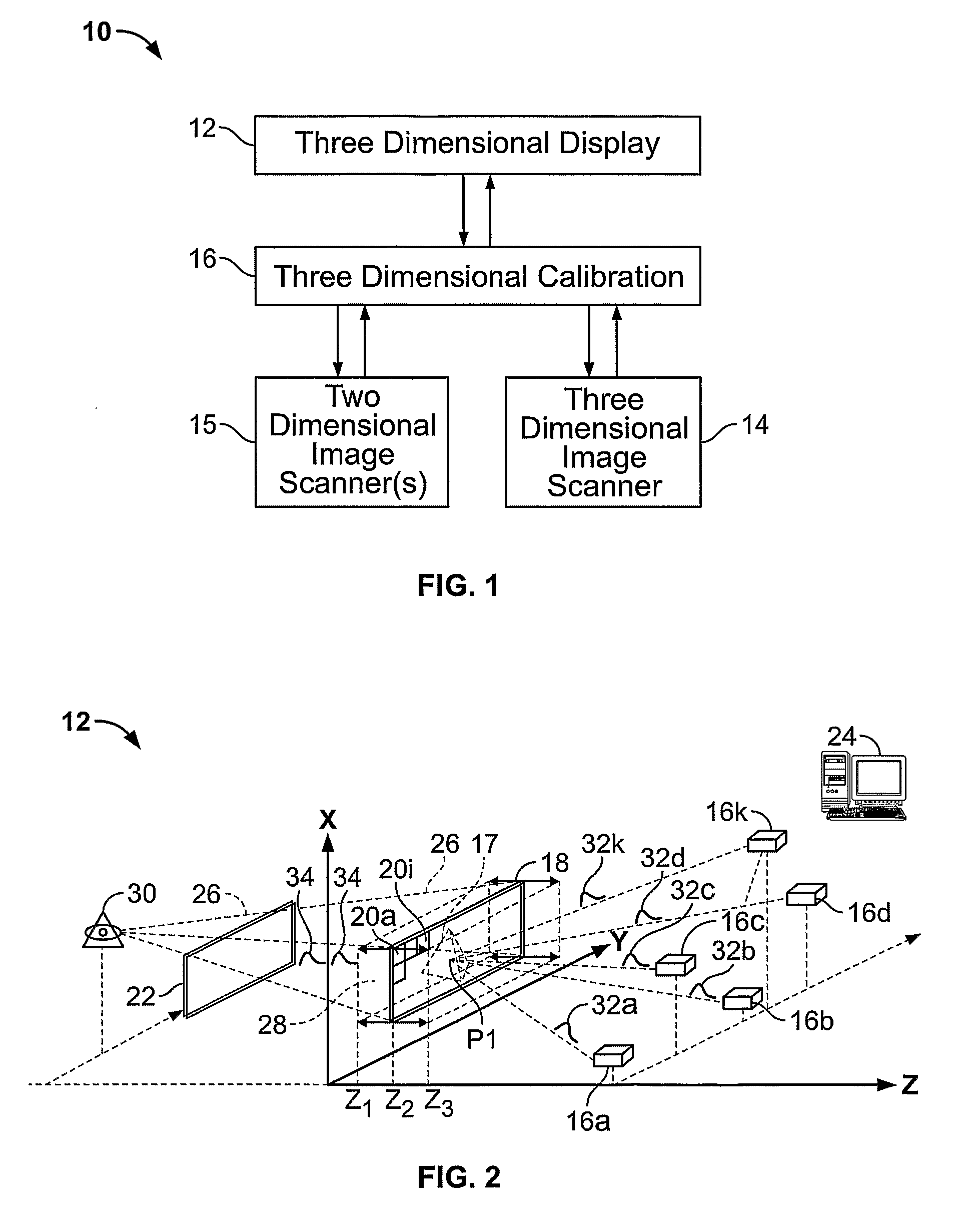
[0075]With reference to FIG. 1, a block diagram of a complete three-dimensional imaging system 10 is depicted. The three-dimensional imaging system 10 includes a three-dimensional display 12, a three-dimensional image scanning device 14, and / or one or more two-dimensional image scanning devices 15, and three-dimensional calibration equipment 16. The three-dimensional image scanning device 14 and / or the two-dimensional image scanning device 15 are employed to generate a three-dimensional image (not shown) to be displayed on the three-dimensional display 12, and to provide data for use by the three-dimensional calibration equipment 16. The three-dimensional calibration equipment 16 calibrates the three-dimensional image scanning device 14 and / or the two-dimensional image scanning device 15. The three-dimensional display 12 and the three-dimensional image scanning device 14 both employ optical pulses and non-linear optics (not shown) to display and record, respectively, a three-dimensi...


PUM


Abstract

A three dimensional imaging system is disclosed which includes a three dimensional display (12), three-dimensional calibration equipment (16), and one or more two-dimensional (15) or three dimensional (14) image scanners. The three-dimensional display (12) uses optical pulses (32a-32k) and a non linear optical mixer (18) to display a three-dimensional image (17). The three-dimensional image (17) is generated in voxels of the display volume (28) as the optical mixer (18) sweeps the display volume (28). The three-dimensional calibration equipment (16) uses a hologram projected proximal to a desired object (164) to calibrate optical imaging devices (162a-162c) and to simplify the combination of the images from one or more optical imaging devices (162a-162c) into three-dimensional information. The three-dimensional image scanner (14) employs optical pulses (136, 138) and a non-linear optical mixer (128) to acquire three-dimensional images of a desired object (134). The three-dimensional image scanner (14) captures both the shape and color of a desired object (134).

Description

CROSS-REFERENCE TO RELATED APPLICATION[0001]This application claims the benefit of U.S. Provisional Application Ser. No. 60 / 533,384 filed Dec. 30, 2003, U.S. Provisional Application Ser. No. 60 / 533,134 filed Dec. 30, 2003, U.S. Provisional Application Ser. No. 60 / 533,305 filed Dec. 30, 2003, and U.S. Provisional Application Ser. No. 60 / 537,773 filed Jan. 20, 2004, the disclosures of which are incorporated herein by reference in their entirety.FIELD OF THE INVENTION[0002]The present invention relates to three-dimensional imaging, and, more particularly, to an apparatus for providing a three-dimensional imaging system which includes a three-dimensional display, a two-dimensional and / or three-dimensional scanning device, and calibration equipment to calibrate the scanning device(s) and to simplify the combination of the images from one or more two-dimensional optical imaging devices into three-dimensional information. The display and the scanning device(s) both employ optical pulses an...

Claims


Application Information

Patent Timeline
Patent Type & Authority Applications(United States)
IPC IPC(8): G06T15/00G09G5/00H04N13/393G09G3/00
CPCH04N13/0207H04N13/0246H04N13/0493H04N13/049H04N13/0253H04N13/254H04N13/246H04N13/393H04N13/207H04N13/39
Inventor KEATING III, JOHN J.
Owner STEVENS INSTITUTE OF TECHNOLOGY
Why Eureka
Try Eureka