
Replaceable lamp module for liquid crystal display

a liquid crystal display and lamp module technology, applied in lighting and heating apparatus, lighting device details, instruments, etc., can solve the problems of increased increased and insufficient luminance of electro luminescence and light emitting diodes, so as to reduce the risk of lamp cable burnout and the failure possibility of hi-pot test.

Active Publication Date: 2008-01-17
AU OPTRONICS CORP
View PDF10 Cites 2 Cited by
  • Summary
  • Abstract
  • Description
  • Claims
  • Application Information

AI Technical Summary

Benefits of technology

"The invention provides a replaceable lamp module for use in a liquid crystal display. The module has a dismantling mechanism that can be easily applied to disassemble the lamp module from the display without pulling the wire connected to the lamp tube, thereby reducing the risk of failure and lamp cable burnout. The module includes a reflector with a concave, opening, or bulge to facilitate disassembly. The reflector has a length difference between its sides. The invention also includes a wire, flexible pads, and a dismantling mechanism on the reflector. The technical effects of the invention are improved reliability and ease of replacement of the lamp module in liquid crystal displays."

Problems solved by technology

Recently, the white light (panchromatic) EL and the light emitting diode as the light source are applied to electrical devices having a smaller-than-4-inches size LCD such as a mobile phone and a personal digital assistant (PDA), because insufficient luminance of the electro luminescence and the light emitting diode is a disadvantage for the use in a larger size LCD.
Unfortunately, in the process of disassembling the conventional lamp tube unit, the operator has to pull the wire connected with the CCFL to make the lamp tube unit detached from the LCD.
This action causes to damage a connection of the wire and the CCFL, resulting in an increase in failure possibility of Hi-pot test and the risk of lamp cable burnout.

Method used


Image

  • Replaceable lamp module for liquid crystal display
  • Replaceable lamp module for liquid crystal display
  • Replaceable lamp module for liquid crystal display

Examples


Embodiment Construction

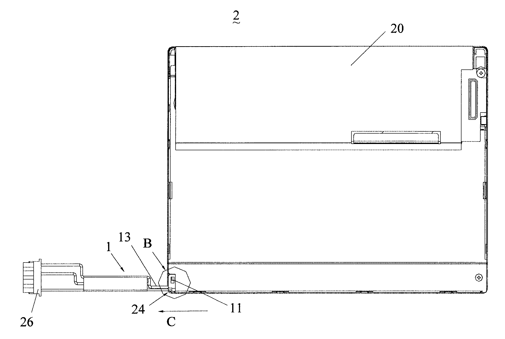
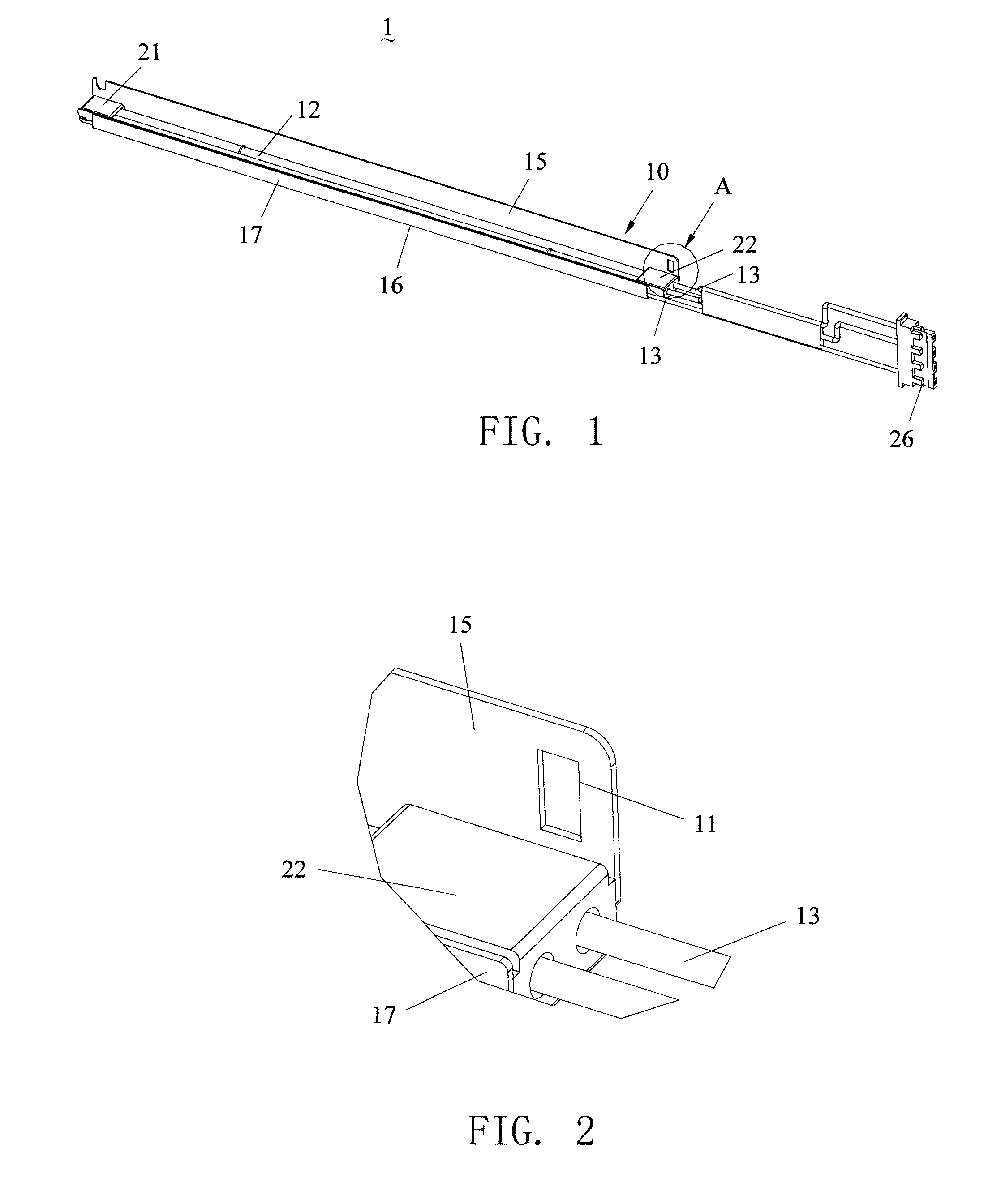
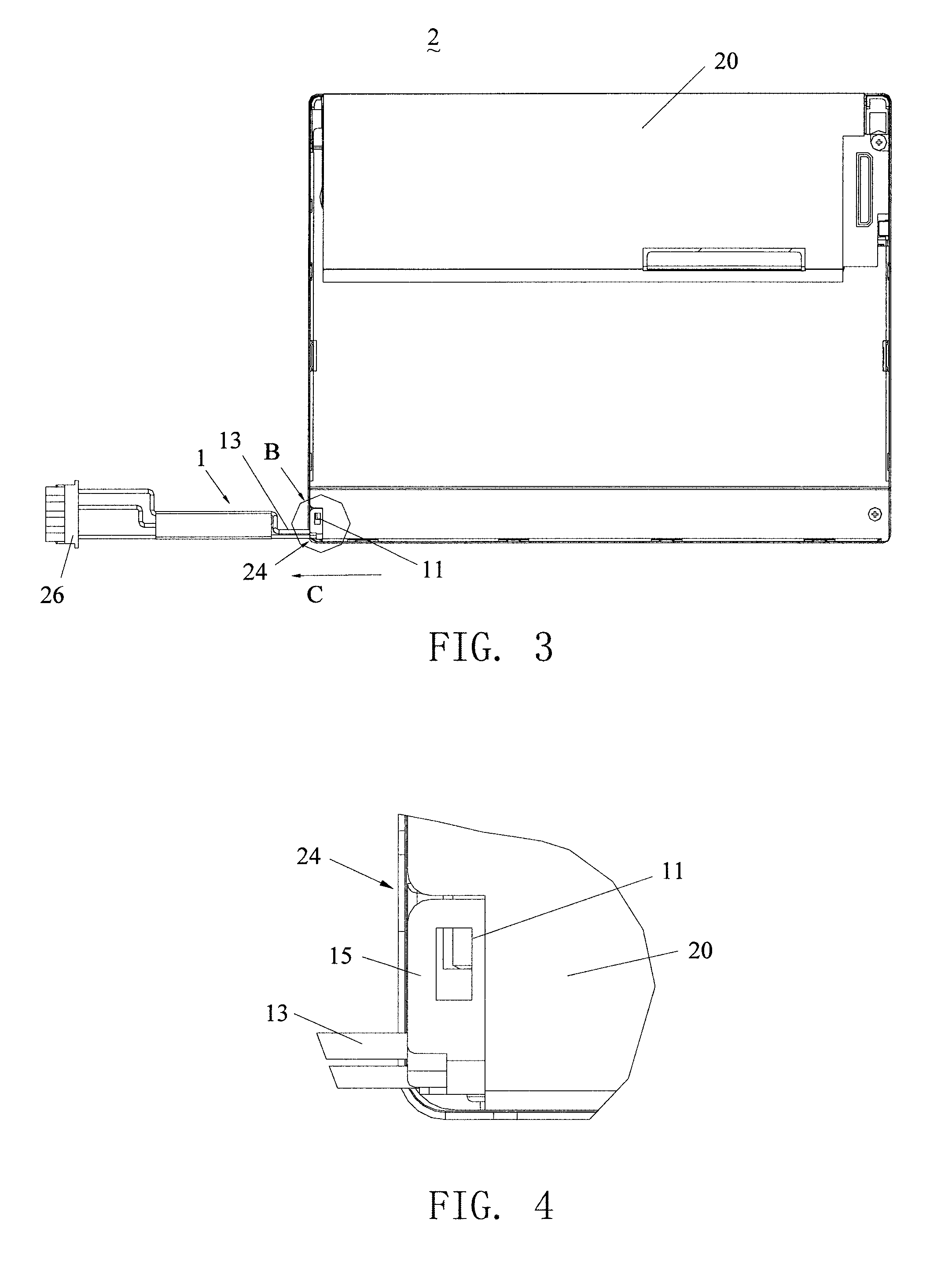
[0021]Please refer to FIGS. 1 and 2. FIG. 1 shows a lamp module 1 in accordance with a preferred embodiment of the present invention. FIG. 2 shows an enlarged diagram of region A shown in FIG. 1. The lamp module 1 for use in a LCD display comprises a reflector 10, a lamp tube 12, a wire 13 and a connector 26. The reflector 10 longitudinally encloses at least side of the lamp tube 12 and defines a dismantling mechanism 11 thereon. One terminal of the wire 13 is electrically connected to one end of the wire 13, bent toward the other end of the lamp tube 12 adjacent to the dismantling mechanism, is electrically connected to a power supply (not shown) via the connector 26.

[0022]The reflector 10 comprises a first side 15, a second side 16 in vertical to the first side 15, and a third side 17 in parallel with the first side 15. The first side 15, the second side 16 and the third side 17 forms a sink for positioning the lamp tube 12. The dismantling mechanism 11 is disposed on an end of th...


PUM


Abstract

A lamp module for use in a liquid crystal display includes a lamp tube, a reflector, a dismantling mechanism disposed on the reflector. The reflector comprises a first side, a second side, and a third side forming a sink, for accommodating the lamp tube and reflecting light from the lamp tube. The dismantling mechanism disposed on the reflector and outside a bezel of the liquid crystal display when the lamp module is assembled to the liquid crystal display. The lamp module is capable of being disassembled from the bezel of the liquid crystal display by applying a force on the dismantling mechanism.

Description

BACKGROUND OF THE INVENTION[0001]1. Field of the Invention[0002]The present invention relates to a replaceable lamp module for use in a liquid crystal display, and more particularly, to a replaceable lamp module with a dismantling mechanism for use in a liquid crystal display.[0003]2. Description of the Related Art[0004]Backlight module including a light source, optical films and a bezel, is employed as a backlight source for a Liquid Crystal Display (LCD). At present, the widely used light source is an Electro Luminescence (EL), a Cold Cathode Fluorescent Lamp (CCFL) and a Light Emitting Diode (LED).[0005]However, the electro luminescence and the light emitting diode are mainly used in small size and single chromatic (green or red) LCD. Recently, the white light (panchromatic) EL and the light emitting diode as the light source are applied to electrical devices having a smaller-than-4-inches size LCD such as a mobile phone and a personal digital assistant (PDA), because insufficien...

Claims


Application Information

Patent Timeline
Patent Type & Authority Applications(United States)
IPC IPC(8): F21V19/00
CPCF21V19/04G02F1/1309G02F1/133604G02F2001/133612G02F2001/133325G02F2001/133328G02F1/133615G02F1/133325G02F1/133328G02F1/133612
Inventor SHAO, TUNG-LIANGYANG, CHI-CHUNCHIEN, YE-HEN
Owner AU OPTRONICS CORP
Learn More