Production method of disk drive device for cleaning subassemblies and disk drive device produced by said production method

a production method and technology which are applied in the direction of data recording, magnetic recording, instruments, etc., can solve the problems that the particles attached during the assembly as described above cannot be removed by a conventional production method of a disk drive device, and the failure of the head crash in the magnetic head, so as to reduce the amount of particles attached to the disk drive device through the production process

Inactive Publication Date: 2011-08-18
SAMSUNG ELECTRO MECHANICS JAPAN ADVANCED TECHNOLOGY CO LTD
View PDF3 Cites 1 Cited by
  • Summary
  • Abstract
  • Description
  • Claims
  • Application Information

AI Technical Summary

Benefits of technology

[0013]According to the embodiment, the particles attached to the disk drive device through the production processes can be reduced, allowing for the reduction in the possibility that TA failure occurring.

Problems solved by technology

Meanwhile, the use of an MR device in an extremely small space may cause thermal asperity failure (hereinafter, referred to as “TA failure”) and head crash failure in the magnetic head.
More specifically, TA failure is a failure where fine foreign particles on the surface of a recording disk come into contact with an MR device when the magnetic head floats and traces, instantaneously producing heat in the MR device by the kinetic energy of the particles while instantaneously heating or cooling the MR device, such that the resistance value of the MR device changes instantaneously and that the changed resistance value is included in a reproduced signal as noise, which prevents the reproduced signal from being correctly read out.
The particles that are attached during the assembly as described above cannot be removed by a conventional production method of the disk drive device, and the general standard of the cleanliness inside of a disk drive device is very low.
When a lot of particles stay, the possibility that TA failure may occur increases in the case where the gap for a magnetic head to float is made small, hindering a disk drive device from having small size and large capacity.

Method used


Image

  • Production method of disk drive device for cleaning subassemblies and disk drive device produced by said production method
  • Production method of disk drive device for cleaning subassemblies and disk drive device produced by said production method
  • Production method of disk drive device for cleaning subassemblies and disk drive device produced by said production method

Examples


Embodiment Construction

[0023]The invention will now be described by reference to the preferred embodiments. This does not intend to limit the scope of the present invention, but to exemplify the invention.

[0024]The invention will now be described in reference to the preferred embodiments (hereinafter, referred to as embodiments). The same or equivalent constituting elements and members illustrated in each drawing shall be denoted by the same reference numerals, and duplicative explanations will be omitted appropriately. The dimensions of members illustrated in each drawing are appropriately enlarged or reduced for easier understanding. Some of members not important for describing the embodiments are omitted from each drawing.

[0025]Preferably, the disk drive device according to the embodiment is used as a hard disk drive (often simply referred to as an HDD) provided with a recording disk. Also, the disk drive device may be an HDD.

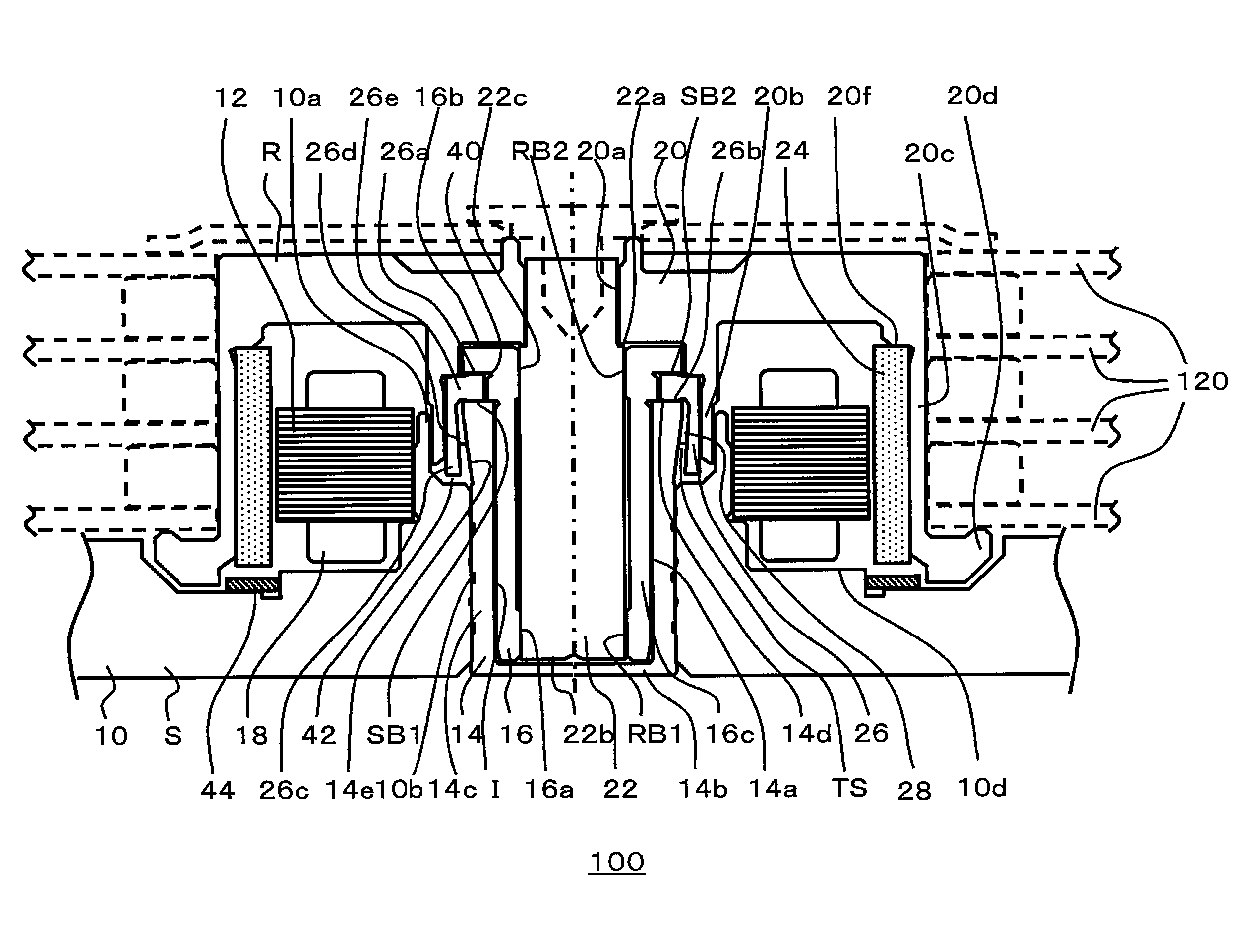
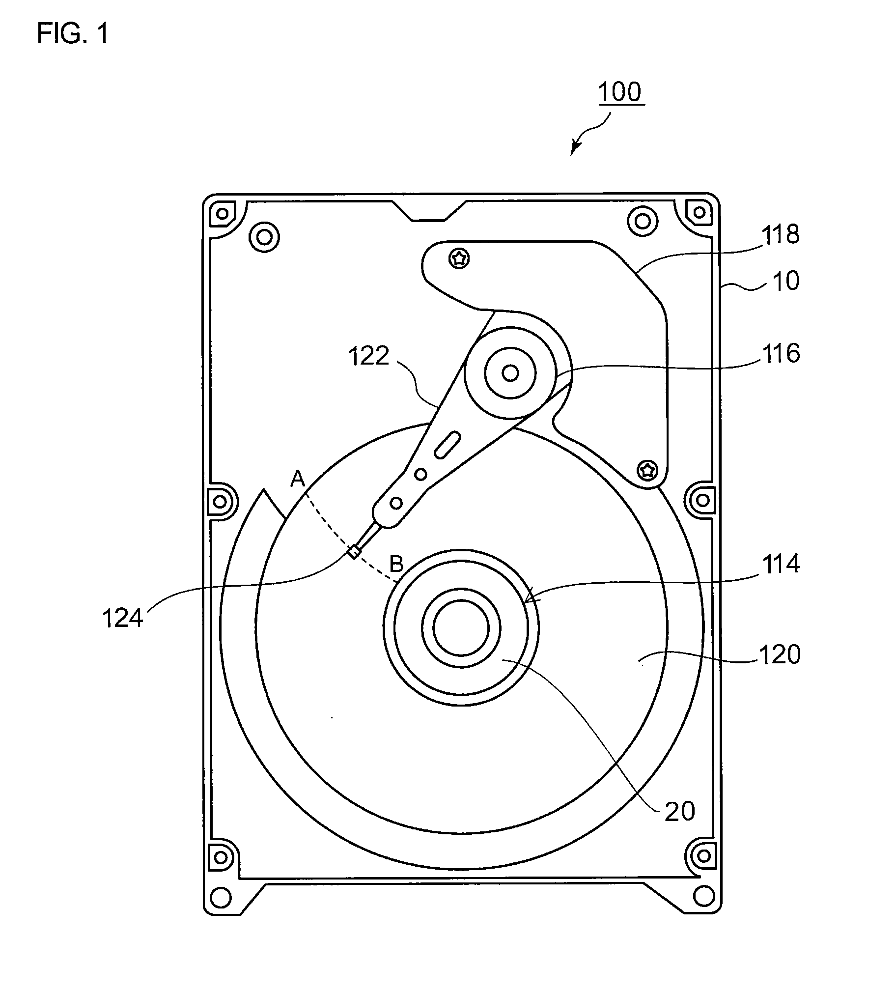
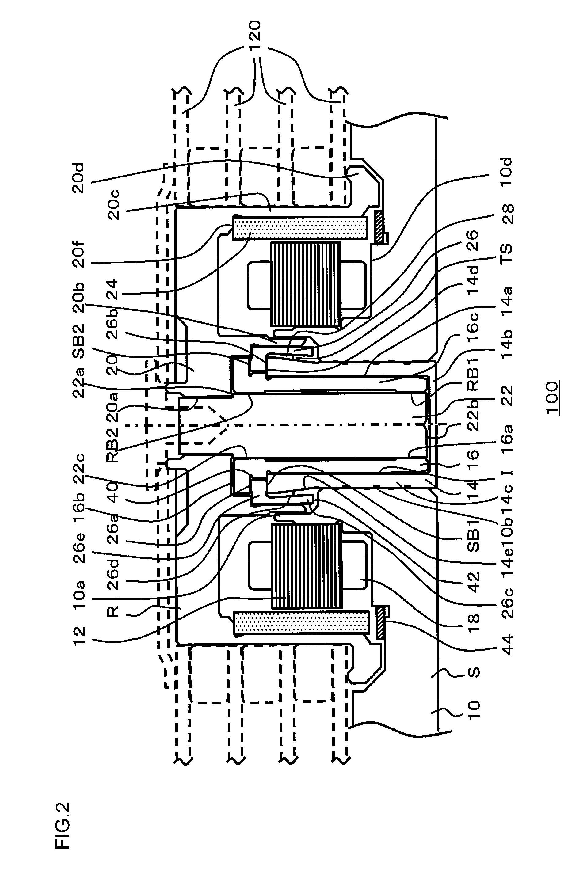
[0026]FIG. 1 is a view showing the internal configuration of a disk drive dev...


PUM

PropertyMeasurementUnit
inclination angleaaaaaaaaaa
temperatureaaaaaaaaaa

Abstract

A production method of a disk drive device includes: an assembling process of assembling a subassembly by incorporating at least a bearing unit in a hub in a clean room; a pouring process of pouring a lubricant in the bearing unit; a cleaning-liquid discharging process of discharging a cleaning liquid to the hub; a cleaning-liquid intake process of taking in the cleaning liquid discharged to the hub; and a sealing process of sealing the subassembly in a seal-material.

Description

CROSS-REFERENCE TO RELATED APPLICATION[0001]This application is based upon and claims the benefit of priority from the prior Japanese Patent Application No. 2010-028972, filed on Feb. 12, 2010, the entire content of which is incorporated herein by reference.BACKGROUND OF THE INVENTION[0002]1. Field of the Invention[0003]The present invention relates to a production method of a disk drive device provided with a bearing unit and to a disk drive device produced by the production method.[0004]2. Description of the Related Art[0005]In recent years, there has been demand for disk drive devices, such as an HDD (Hard Disk Drive), of a smaller size and larger capacity. For example, in a disk drive device that magnetically records data, a recording disk having a recoding track is rotated at high speed, and a magnetic head reads or writes the data while floating over the recoding track, keeping a slight space above the recoding track. In order to provide a disk drive device of a small size and...

Claims


Application Information

Patent Timeline
Patent Type & Authority Applications(United States)
IPC IPC(8): G11B5/82G11B5/127
CPCG11B5/84G11B5/82Y10T29/49703Y10T29/49025G11B19/2045
Inventor AONO, MITSUHIRO
Owner SAMSUNG ELECTRO MECHANICS JAPAN ADVANCED TECHNOLOGY CO LTD
Why Eureka
Try Eureka