
Method of determining node location in cognitive radio network environment and node location determination device for implementing the method

a cognitive radio network environment and node location technology, applied in the direction of location information based services, digital transmission, network topologies, etc., can solve the problem that the fixed location of the relay node may temporarily not be an optimal location for data transmission, the possibility of a communication failure between the transmitting node and the receiving node increases, and the communication failure between the transmitting node and the receiving node is minimized. , the effect of maximum communication efficiency

Active Publication Date: 2021-01-26
AGENCY FOR DEFENSE DEV
View PDF4 Cites 0 Cited by
  • Summary
  • Abstract
  • Description
  • Claims
  • Application Information

AI Technical Summary

Benefits of technology

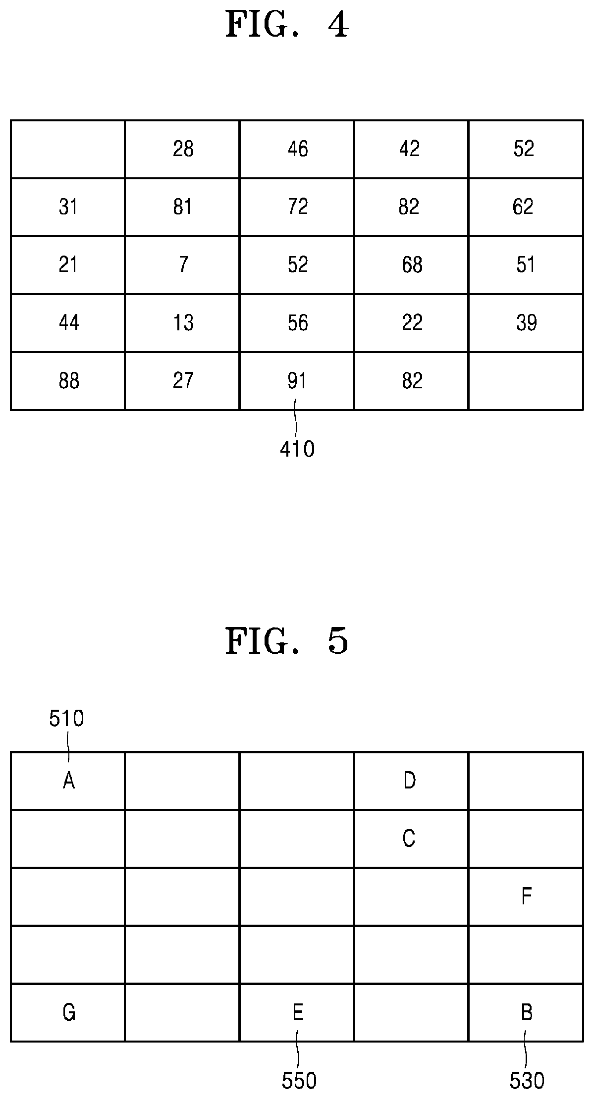
The patent text describes a method for improving communication in a cognitive radio network by collecting location and frequency resource information of secondary receivers and relay nodes, and calculating the ease-of-communication for each segment based on this information. This allows the relay node to move to an optimal segment for maximized communication efficiency, reducing the possibility of communication failures and increasing overall network communication efficiency.

Problems solved by technology

However, when the location of the relay node is fixed, the fixed location of the relay node may temporarily not be an optimal location for data transmission.
For example, in an environment where two or more links exist, data transmission may not be performed smoothly due to interference from other terminals.
As another example, when a signal-to-interference ratio (SIR) of a transmitting node and the SIR of a receiving node are different from each other and an actual SIR sensed by the transmitting node is significantly different from an actual SIR sensed by the receiving node, the possibility of a communication failure between the transmitting node and the receiving node increases.
However, on rainy or foggy days, there are many water droplets and water vapor in the air, which reduces the transmission accuracy of radio waves.

Method used


Image

  • Method of determining node location in cognitive radio network environment and node location determination device for implementing the method
  • Method of determining node location in cognitive radio network environment and node location determination device for implementing the method
  • Method of determining node location in cognitive radio network environment and node location determination device for implementing the method

Examples


Embodiment Construction

Technical Problem

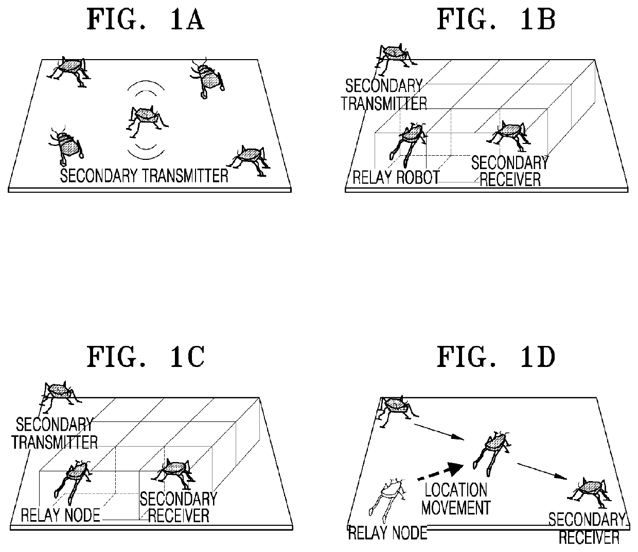
[0007]Provided are a method of determining the location of a mobile relay node in order to minimize the possibility of a communication failure in a process of data transmission through a secondary transmitter, a relay node, and a secondary receiver in a cognitive radio network environment, and a device for implementing the method.

Solution to Problem

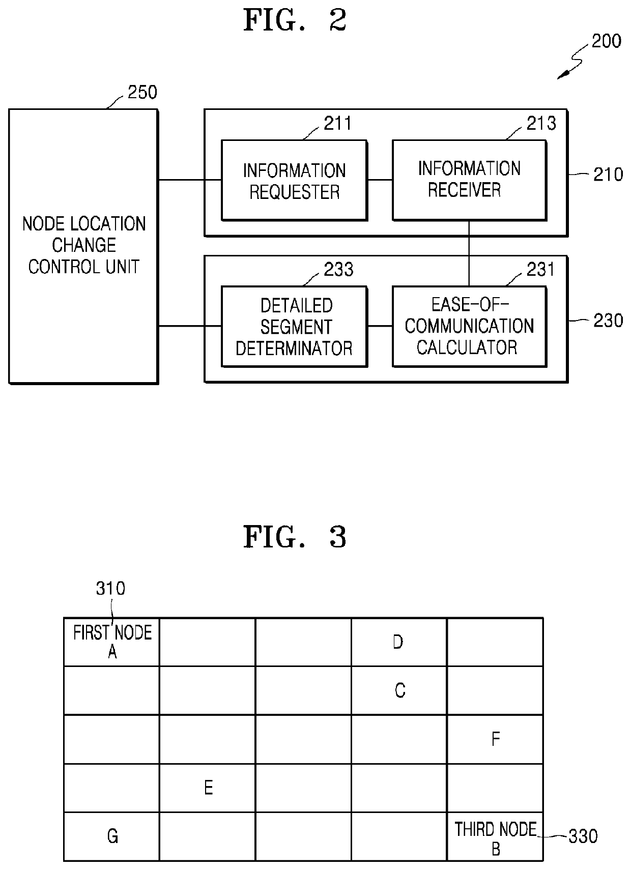
[0008]According to an aspect of the present disclosure, a method of determining a node location in a cognitive radio network environment in which data is transmitted from a first node to a third node via a second node, includes information requesting wherein the first node transmits an information request signal to a plurality of second nodes in a preset segmented region; information receiving wherein the first node receives, from the second nodes, location information and frequency resource information for each second node corresponding to the transmitted information request signal; and segment determining wherein the fi...


PUM


Abstract

Provided is a method of determining a node location in a cognitive radio network environment in which data is transmitted from a first node to a third node via a second node. The method includes information requesting wherein the first node transmits an information request signal to a plurality of second nodes in a preset segmented region; information receiving wherein the first node receives, from the second nodes, location information and frequency resource information for each second node corresponding to the transmitted information request signal; and segment determining wherein the first node determines one segment in the segmented region based on the received location information and frequency resource information.

Description

TECHNICAL FIELD[0001]The present disclosure relates to a method of determining a node location in a cognitive radio network environment and a node location determination device for implementing the method, and more particularly, to a method of maximizing a frequency efficiency by properly adjusting locations of a plurality of relay nodes located between a secondary transmitter and a secondary receiver in a cognitive radio network environment and a device for implementing the method.BACKGROUND ART[0002]Cognitive radio is a radio technology that operates by measuring a radio propagation environment and setting operating parameters of a radio device in accordance with the measured radio propagation environment. For example, technology for maximizing a transmission capacity of a radio device in accordance with channel characteristics, technology for minimizing interference between devices, technology for facilitating interoperability between different types of systems, and technology fo...

Claims


Application Information

Patent Timeline
Patent Type & Authority Patents(United States)
IPC IPC(8): H04W16/10H04L27/00H04W16/14H04W64/00H04W72/04
CPCH04W16/10H04L27/0006H04W16/14H04W64/003H04W72/0453H04W4/02H04W16/18H04W64/006H04W84/005H04W88/04H04W64/00
Inventor PARK, SANG CHEONHONG, YOUNG TAEKKIM, JEE MINKIM, SEONG LYUN
Owner AGENCY FOR DEFENSE DEV
Learn More