

Cuffed fan blade modifications
- Summary
- Abstract
- Description
- Claims
- Application Information
AI Technical Summary
Problems solved by technology
Method used
Image

Examples
Embodiment Construction
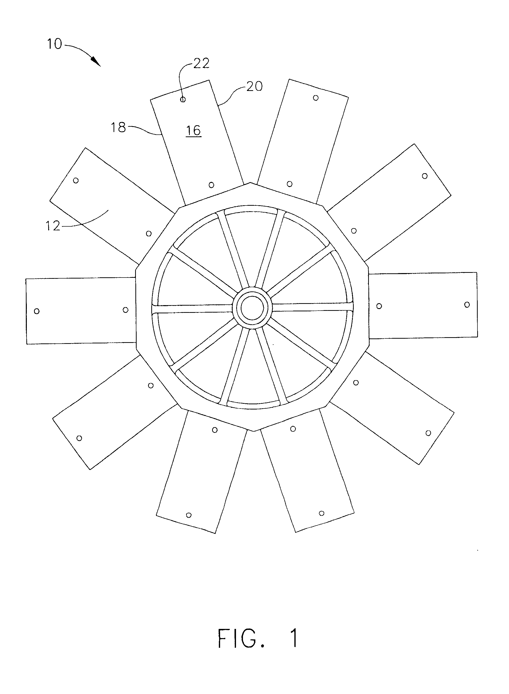
[0022] Referring now to the drawings in detail, wherein like numerals indicate the same elements throughout the views, FIG. 1 shows exemplary fan hub (10), which may be used to provide a fan having fan blades (30 or 50).
[0023] In the present example, fan hub (10) includes a plurality of hub mounting members (12) to which fan blades (30 or 50) may be mounted. In one embodiment, fan hub (10) is coupled to a driving mechanism for rotating fan hub (10) at selectable or predetermined speeds. A suitable hub assembly may thus comprise hub (10) and a driving mechanism coupled to hub (10). Of course, a hub assembly may include a variety of other elements, including a different hub, and fan hub (10) may be driven by any suitable means. In addition, fan hub (10) may have any suitable number of hub mounting members (12).
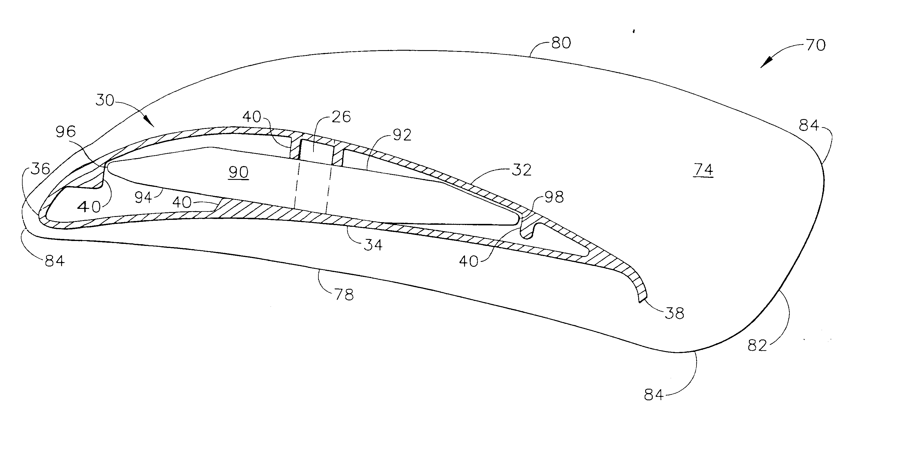
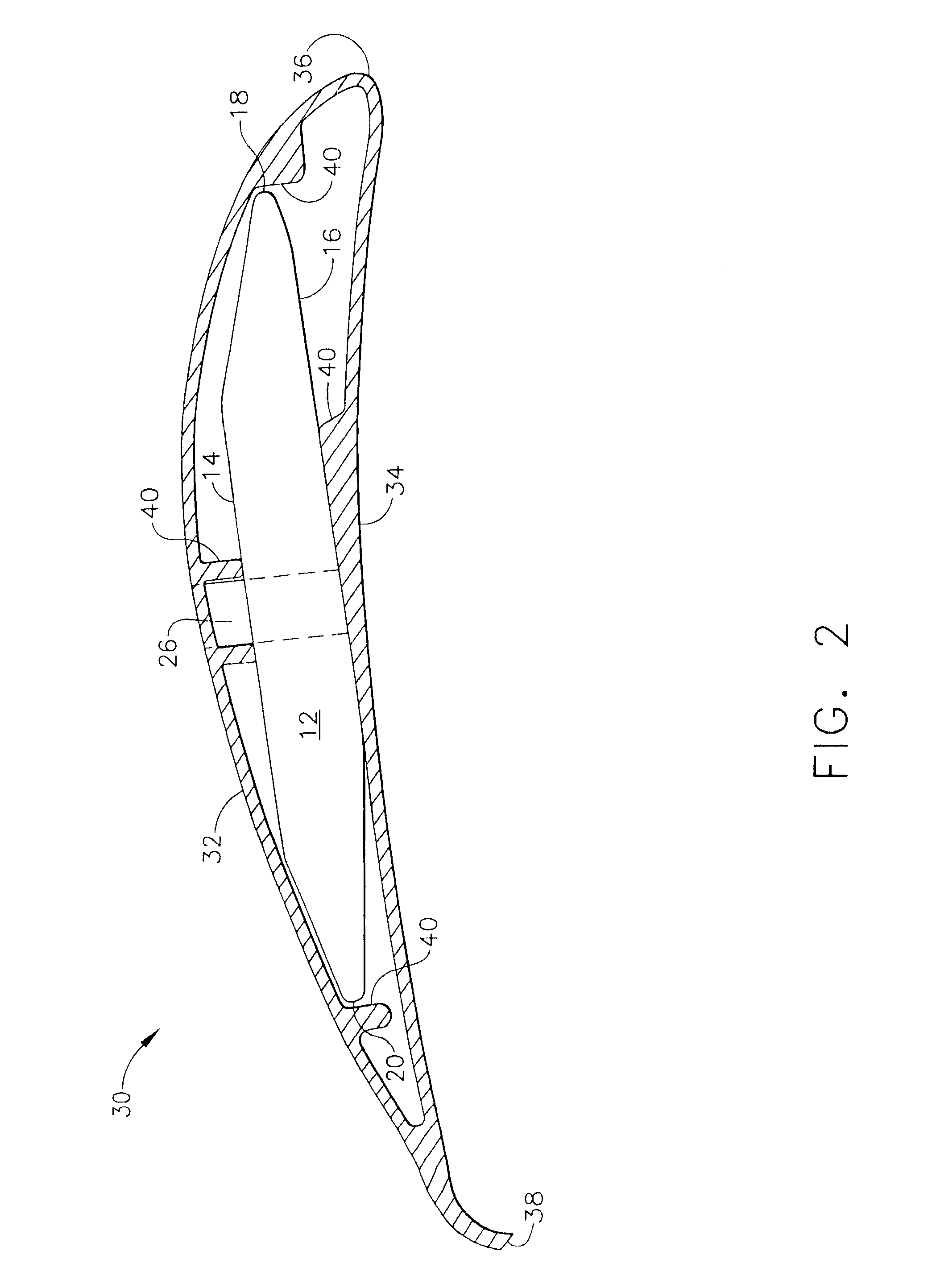
[0024] As shown in FIGS. 1 through 3, each hub mounting member (12) has top surface (14) and bottom surface (16), which terminate into leading edge (18) and trailing edge (20)...
PUM
 Abstract
Description
Claims
Application Information