Laser projection system to facilitate layup of complex composite shapes

a composite shape and projection system technology, applied in the field of composite airfoils, can solve the problems of blade material erosion, blade fracture or piercing, degrade the performance of the fan and engine, etc., and achieve the effects of reducing the incidence of scrapping material, increasing the speed of ply lay-up, and increasing the accuracy of ply lay-up

Inactive Publication Date: 2005-01-18
GENERAL ELECTRIC CO
View PDF15 Cites 80 Cited by
  • Summary
  • Abstract
  • Description
  • Claims
  • Application Information

AI Technical Summary

Benefits of technology

Among the advantages provided by the present invention is increased ply lay-up speed and increased ply lay-up accuracy, with decreased incidence of scrapping material, during manufacture of a light weight composite blade. The blade is highly resistant to delamination and failure caused by bending and impact from FOD such as debris and bird ingestion, so accurate ply

Problems solved by technology

Smaller objects can erode the blade material and degrade the performance of the fan and engine.
Impact by larger objects may fracture or pierce the blades.
Portions of an impacted blade can be torn loose and cause extensive secondary damage to the downstream blades and other engine components.
In this regard, the consequences of foreign object damage are greatest in the low pressure compressors and fans of high bypass gas turbine engines.
However, these components offer the greatest potential in weight reduction due to their size.
One particular FOD-related failure mode of composite fan blades is bending and delamination of the blade when it is struck by a heavy object such as a bird, particularly in a region near the radially outward blade tip.
This, in turn, can result in secondary engine damage as the blade fragments, including the leading edge protection strip, are ingested through the engine.
This significantly increases the torsional frequency of the blade.
Th

Method used


Image

  • Laser projection system to facilitate layup of complex composite shapes
  • Laser projection system to facilitate layup of complex composite shapes
  • Laser projection system to facilitate layup of complex composite shapes

Examples


Embodiment Construction

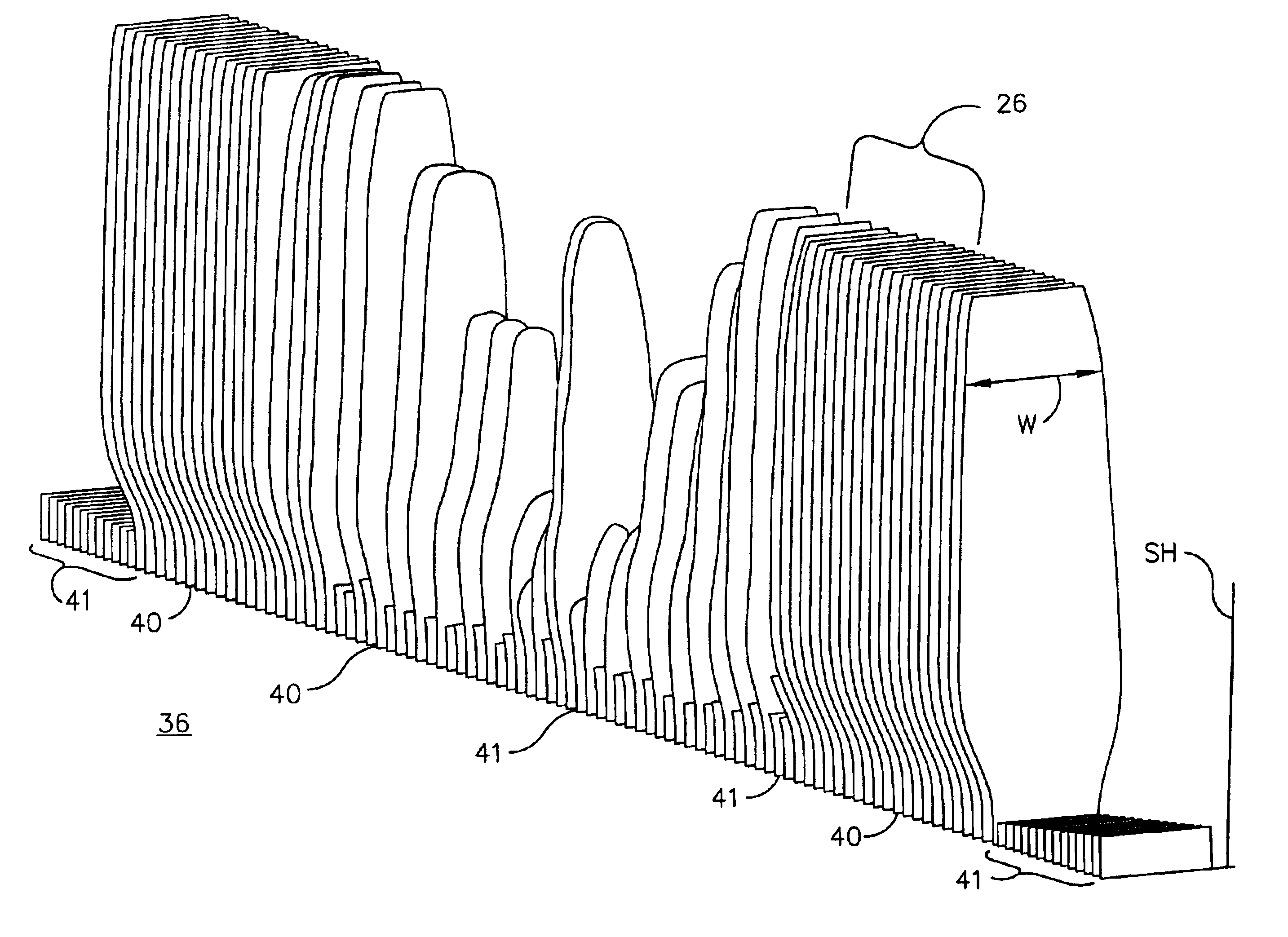
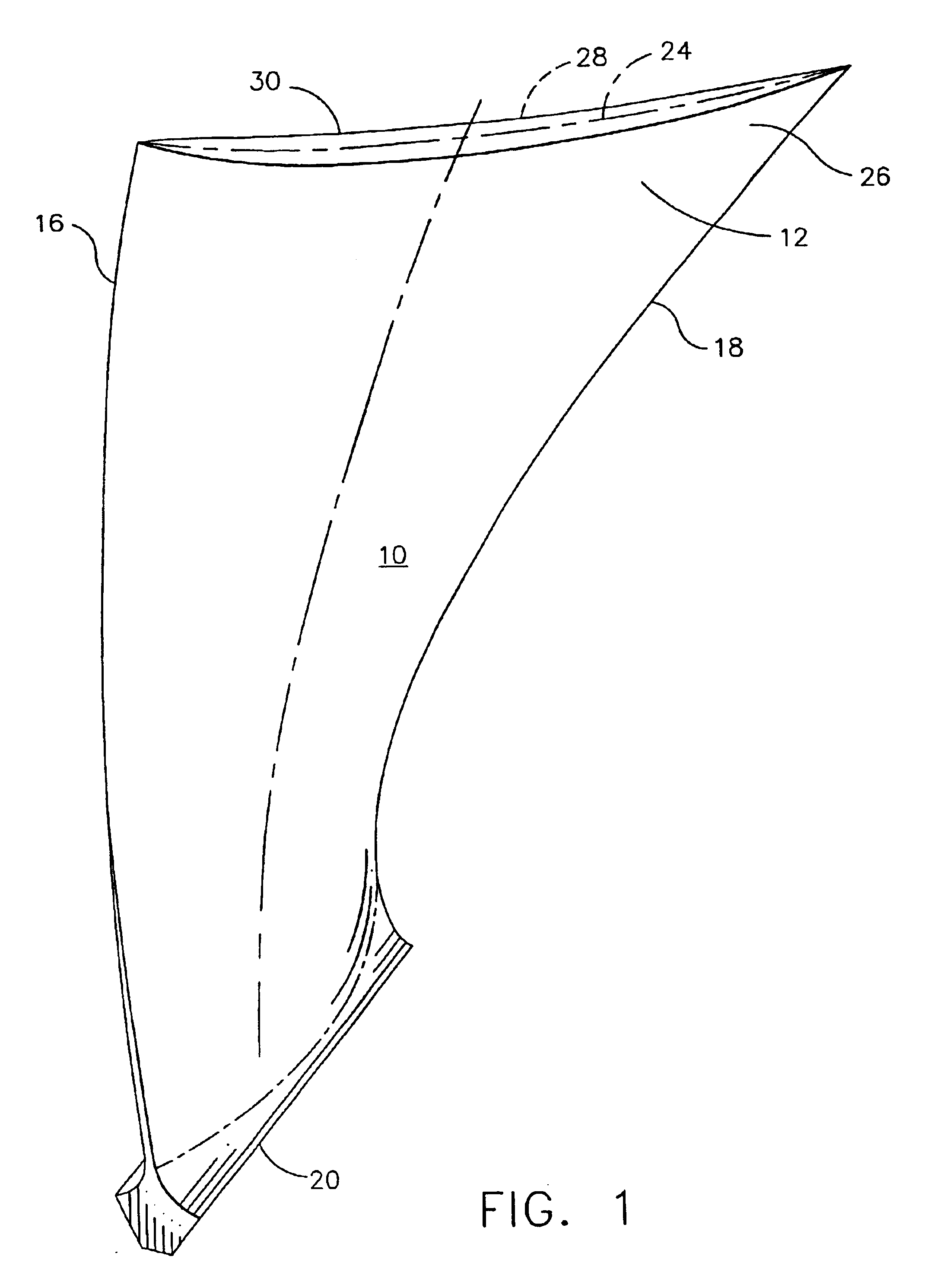
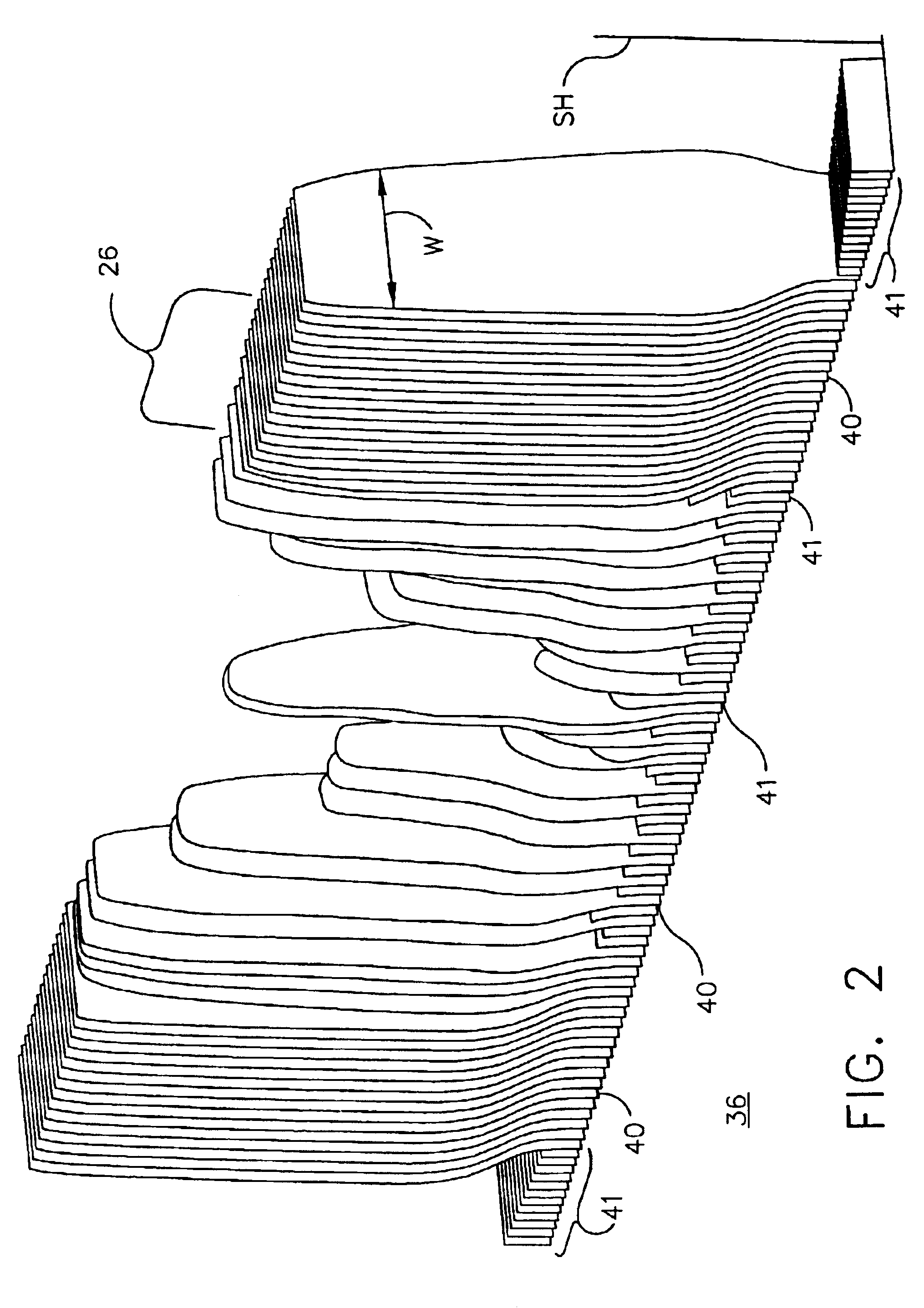
Illustrated in FIG. 1 is a composite fan blade 10 for a high bypass ratio fanjet gas turbine engine having a composite airfoil portion 12 typically including a leading edge 16 and a trailing edge 18. Composite airfoil portion 12 extends radially outward from a root portion 20 to an extent generally defining its span and includes a centerplane 24 that generally divides airfoil portion 12 into two parts that culminate in the convex side 26 and the concave side 28 of the airfoil portion 12 of the blade 10. Composite blade 10 is made up of fiber reinforced laminations 30 formed from a composite material lay-up generally indicated at 36, in FIG. 2, of fiber reinforced prepreg plies 30. As used herein, the terms “lamination” and “ply” are synonymous and the term “prepreg” is used in the art to describe the laminations of fibers impregnated with a matrix of uncured or partially cured resin. The airfoil plies 40 are essentially those individual plies that extend outward to form the airfoil ...


PUM

PropertyMeasurementUnit
Angleaaaaaaaaaa
Angleaaaaaaaaaa
Pressureaaaaaaaaaa

Abstract

The present invention provides a process for the lay-up of a composite laminate article, the article produced by this process, and the apparatus used to produce the composite laminate article. The composite laminate article may be, for example, an airfoil, particularly useful as a fan blade in a large high bypass ratio turbofan engine, wherein the blade is generally regarded as large and having a high degree of twist. In a preferred embodiment, the present invention provides a process for laying up a composite laminate article comprising a) reading a data set to enable the projection of an image of a ply section onto a work surface, the image indicating a ply section target point; b) laying up a ply section of composite laminating material within the image, wherein the ply section first contacts the work surface at the target point; and c) repeating steps (a)-(b) until the composite laminate article is complete. In a second preferred embodiment, the present invention provides for a lamination apparatus for use in making a composite laminate article comprising a work surface for receiving, in a predetermined sequence, a plurality of ply sections of composite laminating material; a laser projection system using predetermined projection points for outlining an image of a ply section onto the work surface, the image further indicating a ply section target point for making first contact of the ply section with the work surface; and a data set for providing the predetermined projection points to the laser projection system.

Description

FIELD OF THE INVENTIONThis invention relates to composite airfoils and their manufacture and more particularly to a composite fan blade having unidirectional fiber laminates arranged by utilizing a rapidly-scanned laser system to project a precise image onto a precisely located region of a work surface, the image including a start indicator for precisely locating a first point of contact for lay-up of each laminate or prepreg.BACKGROUND OF THE INVENTIONIn recent years, the relatively heavy metal blades and vanes of fluid flow machines such as gas turbine engine fans and compressors have been replaced with lighter composite materials. These composite blades and vanes are fabricated to have high strength, and are made from plies comprising elongated fibers in a light weight matrix.Over the years the term composite has had several meanings regarding the use of two or more materials having different properties. In the aerospace industry, the term composite has come to be defined as a ma...

Claims


Application Information

Patent Timeline
IPC IPC(8): B29C70/04B29C70/34B29C70/54F01D5/28
CPCB29C70/34B29C70/541F01D5/286F01D5/282B29L2031/08Y02T50/673Y02T50/672F05D2220/36F05D2300/6034Y02T50/60
Inventor EVANS, CHARLES R.BALDWIN, JACK W.WELSH, SCOTT A
Owner GENERAL ELECTRIC CO
Why Eureka
Try Eureka