Tip cambered swept blade

a technology of cambered blades and turbine blades, which is applied in the direction of marine propulsion, vessel construction, other chemical processes, etc., can solve the problems of limited fan loading and high complexity of turbofan design

Active Publication Date: 2007-10-18
GENERAL ELECTRIC CO
View PDF28 Cites 81 Cited by
  • Summary
  • Abstract
  • Description
  • Claims
  • Application Information

AI Technical Summary

Problems solved by technology

However, fan loading is limited by stall, flutter, or other instability parameters of the air being pressurized.
The resulting turbofan design is a highly complex design with three dimensional variation of the pressure and suction sides of the individual airfoils across their axial chord and over their radial span.

Method used


Image

  • Tip cambered swept blade
  • Tip cambered swept blade
  • Tip cambered swept blade

Examples


Embodiment Construction

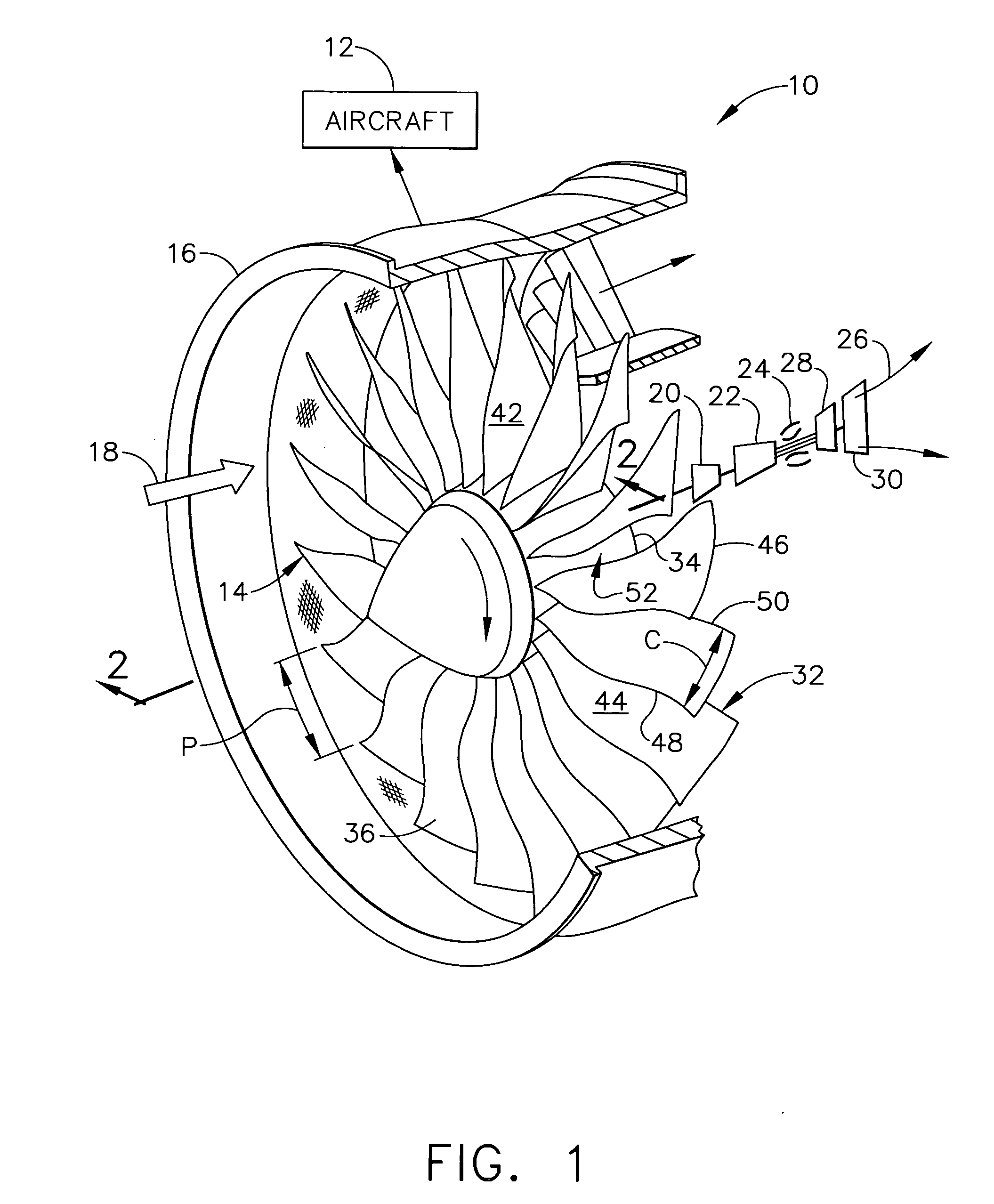
[0027] Illustrated in FIG. 1 is a gas turbine engine 10 configured for powering an aircraft 12 in flight, and suitably mounted therein. The engine is axisymmetrical about a longitudinal or axial centerline axis and includes a fan or turbofan 14 suitably mounted coaxially inside a surrounding annular fan casing 16.

[0028] During operation, ambient air 18 enters the inlet end of the fan 14 and is pressurized thereby for producing propulsion thrust for propelling the aircraft in flight. A portion of the fan air is suitably channeled in turn through a low pressure or booster compressor 20 and a high pressure compressor 22 which further pressurize the air in turn.

[0029] The pressurized air is mixed with fuel in an annular combustor 24 for generating hot combustion gases 26 which are discharged in the downstream direction. A high pressure turbine (HPT) 28 first receives the hot gases from the combustor for extracting energy therefrom, and is followed in turn by a low pressure turbine (LP...


PUM


Abstract

A fan blade includes an airfoil having opposite pressure and suction sides extending in span between a root and tip, and extending in chord between opposite leading and trailing edges. From root toward tip, the airfoil includes increasing stagger and decreasing camber, and increasing chord length to barrel the airfoil along both the leading and trailing edges. The airfoil further includes forward aerodynamic sweep at the tip, and non-forward aerodynamic sweep between the maximum barrel and the root.

Description

[0001] This is a Continuation-in-part of copending U.S. patent application Ser. No. 11 / 100,752, filed Apr. 7, 2005, and incorporated herein by reference.BACKGROUND OF THE INVENTION [0002] The present invention relates generally to gas turbine engines, and, more specifically, to turbofan aircraft engines. [0003] In a turbofan engine air is pressurized in a compressor and mixed with fuel in a combustor for generating hot combustion gases. A high pressure turbine (HPT) extracts energy from the combustion gases to power the compressor. A low pressure turbine (LPT) extracts additional energy from the combustion gases to power the fan disposed upstream from the compressor. [0004] The primary design objective of aircraft turbofan engines is to maximize efficiency thereof for propelling an aircraft in flight, and correspondingly reduce fuel consumption. Accordingly, the various cold and hot section rotor and stator components which define the internal flow passages for the pressurized air a...

Claims


Application Information

Patent Timeline
Patent Type & Authority Applications(United States)
IPC IPC(8): B64C27/46
CPCF01D5/141F02K3/06Y02T50/672Y02T50/673F05D2220/326F05D2220/36F04D29/324F05D2250/70F05D2250/71F05D2250/711F05D2250/712Y10S416/05F05D2220/327Y02T50/60F04D29/384
Inventor WADIA, ASPI RUSTOMSZUCS, PETER NICHOLASFARSON, MAX ROBERTWILSON, VIRGINIA LOUISESOLOMON, WILLIAM JOSEPH
Owner GENERAL ELECTRIC CO
Why Eureka
Try Eureka