Fan blade curvature distribution for high core pressure ratio fan

a fan blade and high core pressure ratio technology, applied in the direction of propellers, air transportation, water-acting propulsive elements, etc., can solve the problems of reducing the overall engine efficiency and stability, and achieve the effect of improving the profil

Active Publication Date: 2007-04-17
PRATT & WHITNEY CANADA CORP
View PDF16 Cites 77 Cited by
  • Summary
  • Abstract
  • Description
  • Claims
  • Application Information

AI Technical Summary

Benefits of technology

[0005]One object of the present invention is to provide a fan blade of an aircraft gas turbine engine, with an enhanced profile.
[0006]In accordance with one aspect of the present invention, there is a method provided for reducing vortex promotion of a rotor blade used in a high core pressure ratio fans. The blade has a plurality of sections extending from a hub to a tip thereof. The method comprises providing a curvature distribution to a first blade section immediately adjacent to the hub such that a major turning of a suction side of the respective sections is located near a trailing edge of the blade, thereby increasing an angle of the section at a suction side between the trailing edge and a periphery of the hub.
[0010]The present invention advantageously achieves the required high core PR profile of a high core pressure ratio fan while minimizing the promotion of a corner vortex, thereby improving the airfoil flow quality of the fan, and thus improving an overall efficiency and stability of the engine performance.

Problems solved by technology

Such an acute angle can help create and / or worsen a corner vortex at the trailing edge of the blade, potentially adversely affecting the quality of airflow at the hub area feeding into downstream blade rows of the compressor, and thereby reducing the overall engine efficiency and stability.

Method used


Image

  • Fan blade curvature distribution for high core pressure ratio fan
  • Fan blade curvature distribution for high core pressure ratio fan
  • Fan blade curvature distribution for high core pressure ratio fan

Examples


Embodiment Construction

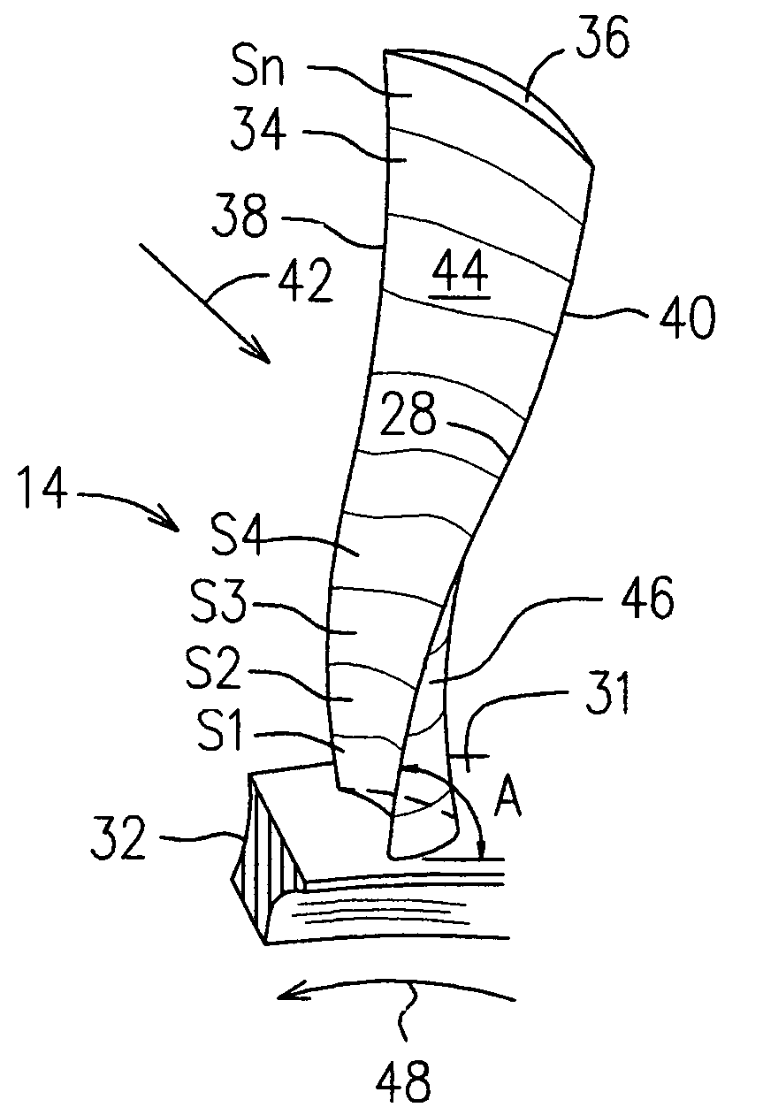
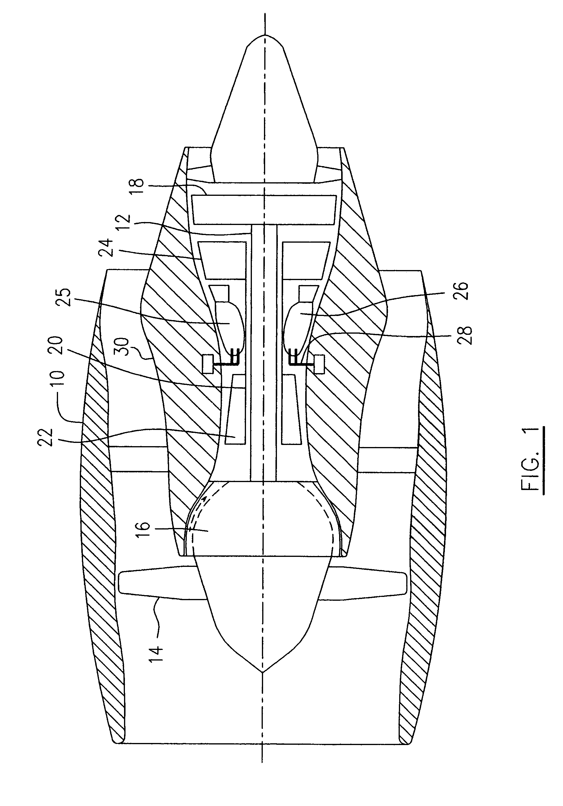
[0019]A turbofan gas turbine engine illustrated schematically in FIG. 1 incorporates an embodiment of the present invention, presented as an example of the application of the present invention, and includes a housing or nacelle 10, a low pressure spool assembly seen generally at 12 which includes a high core pressure ratio fan 14, low pressure compressor 16 and low pressure turbine 18, and a high pressure spool assembly seen generally at 20 which includes a high pressure compressor 22 and a high pressure turbine 24. There is provided a burner seen generally at 25 which includes an annular combustor 26 and a plurality of fuel injectors 28 for mixing liquid fuel with air and injecting the mixed fuel / air flow into the annular combustor to be ignited for generating combustion gases. The high core pressure ratio fan 14 can also be used in other types of turbofan gas turbine engines, for example, a boost-less gas turbine engine which does not include the low pressure compressor 16.

[0020]I...


PUM


Abstract

A method for reducing vortex promotion of a rotor blade used in high core PR fans comprises shifting a curvature distribution of a blade section immediately adjacent to the hub such that a major turning of the suction side of the section is located near a trailing edge of the blade.

Description

FIELD OF THE INVENTION[0001]The present invention relates to an aircraft gas turbine engine, and more particularly to a rotor blade of an aircraft gas turbine engine, with an enhanced profile.BACKGROUND OF THE INVENTION[0002]A boost-less gas turbine engine does not include a boost compressor stage and therefore typically includes a high core pressure ratio (PR) fan which is adapted to compensate for the missing boost stage.[0003]Conventional high core PR fan blades are usually configured with extreme blade turning immediately above the fan hub, which creates a very acute local angle between the blade suction side and the fan hub towards the blade trailing edge. Such an acute angle can help create and / or worsen a corner vortex at the trailing edge of the blade, potentially adversely affecting the quality of airflow at the hub area feeding into downstream blade rows of the compressor, and thereby reducing the overall engine efficiency and stability. Efforts have been made to solve thi...

Claims


Application Information

Patent Timeline
Patent Type & Authority Patents(United States)
IPC IPC(8): F01D5/14F03B3/12F04D29/68
CPCF01D5/141F04D29/681Y02T50/673F05D2250/70Y02T50/60
Inventor DUTTON, RONALD JAMESMACDONALD, KIMBERLEY ANN
Owner PRATT & WHITNEY CANADA CORP
Why Eureka
Try Eureka