Spice bottle

a spice bottle and spice technology, applied in the field of spice bottles, can solve the problems of spice bottles lacking novelty and decorative effect, high consumption of power, and insufficient power supply of batteries

Inactive Publication Date: 2008-01-17
LIN MING KUEI
View PDF1 Cites 13 Cited by
  • Summary
  • Abstract
  • Description
  • Claims
  • Application Information

AI Technical Summary

Benefits of technology

[0003]Therefore it is a primary object of the present invention to provide a spice bottle composed of a spice container, a transparent liquid container and an container for electronic parts. The spice container is disposed on upper part of the spice bottle so as to sprinkle spices from holes on top side while the transparent liquid container is filled with transparent liquid and a plurality of differently colored lustrous foil fragments floating inside the liquid. The container for electronic parts is arranged with a circuit board, a battery holder, vibration switch and a plurality of LED (light-emitting diode) lamps. Light emitted from the LED lamps illuminates into the transparent liquid container. Thus while shaking the spice bottle for adding spices on food, the lustrous foil fragments floating inside the transparent liquid container is driven to flow freely by the shaking force. At the same time, the LED lamps are turned on by vibration switch so as to illuminate light into the transparent liquid container. Thus the lustrous foil fragments reflects the light to have dynamic lighting effect. Therefore, the spice bottle is added with novelty and decorative effect.

Problems solved by technology

However, conventional lamp with 1 lustrous foil fragments uses heat from the light bulb as a driving force, this consumes a lot of power and thus batteries can't provide enough power.
However, such kind of spice bottles are only used as containers without any other added value such as special effect lighting.
Thus such spice bottles lack novelty and decorative effect.

Method used


Image

  • Spice bottle
  • Spice bottle
  • Spice bottle

Examples


Embodiment Construction

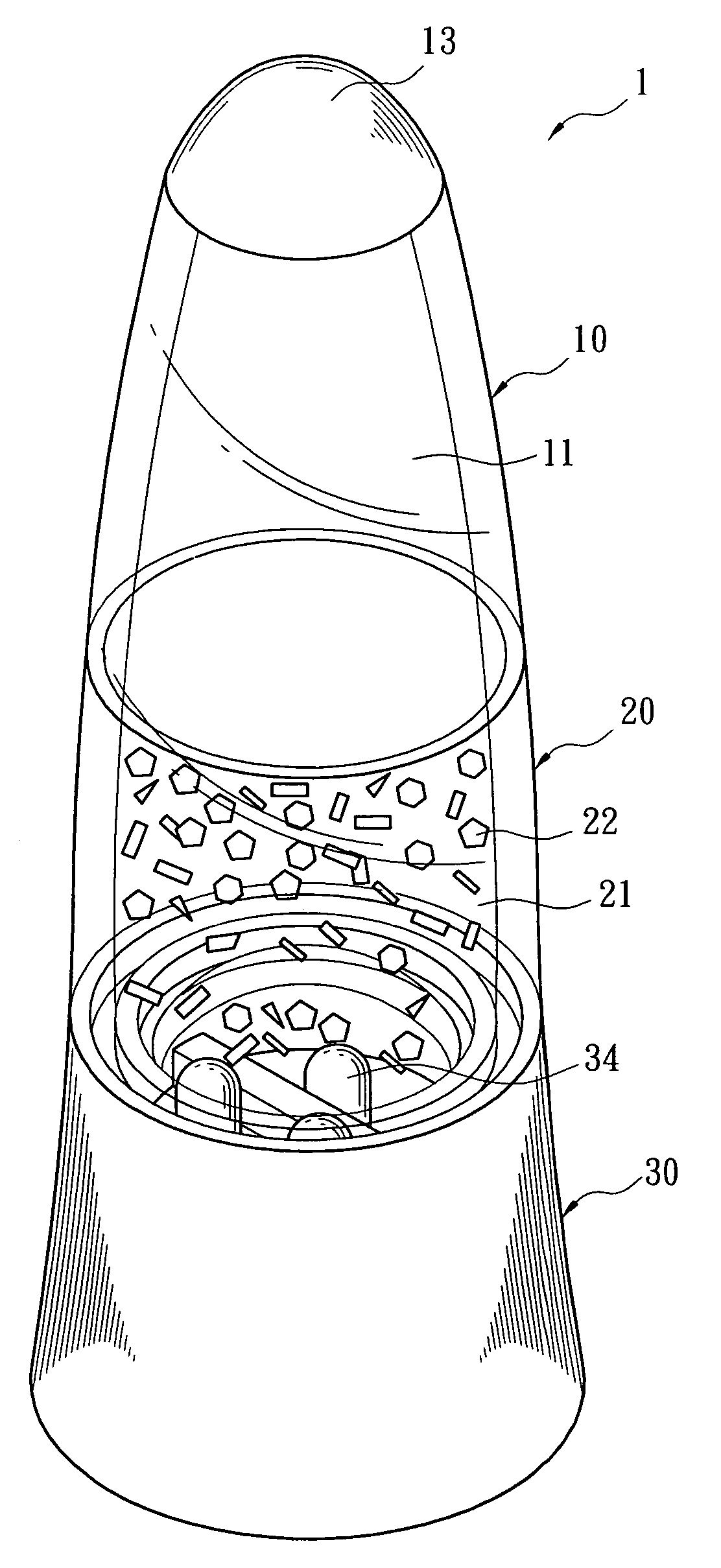
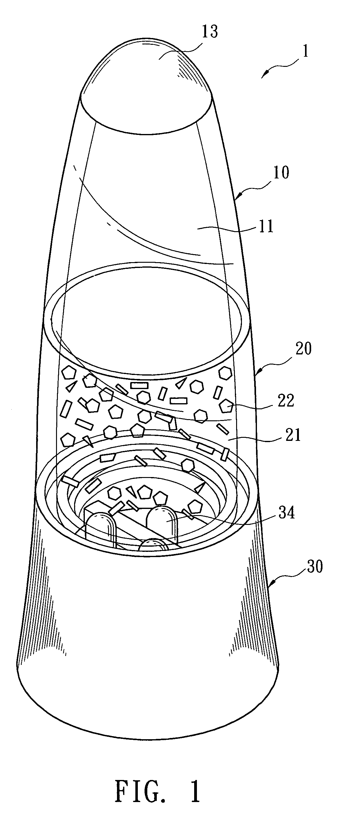
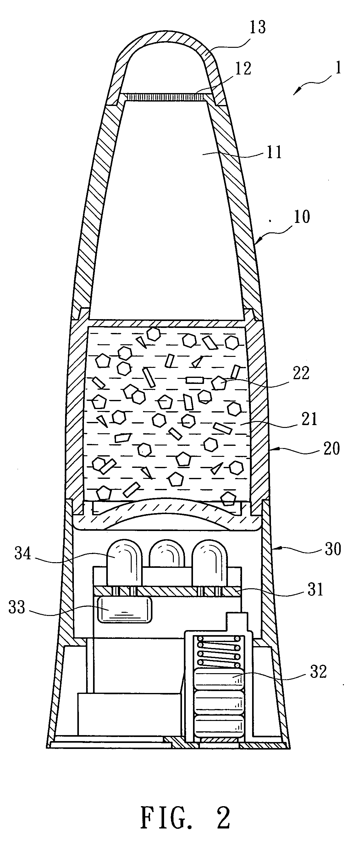
[0010]Refer to FIG. 1&FIG. 2, a spice bottle 1 according to the present invention consists of a spice container 10, a transparent liquid container 20 and an container for electronic parts 30. The spice container 10 is disposed on upper part of the spice bottle 1 and an inner space 11 thereof is for filling spices such as salt or pepper that is used often on table. Holes for pouring spices disposed on top of the a spice container 10 and a cap 13 may arranged on the holes 12. The transparent liquid container 20 is a closed container for liquid and is arranged under the spice container 10. Transparent liquid 21 is filled inside the transparent liquid container 20 and a plurality of differently colored lustrous foil fragments flows inside the liquid 21, being displayed through a transparent housing of the liquid container. The container for electronic parts 30 including a circuit board 31, a battery holder 32, a vibration switch 33 and a plurality of LED lamps 34 is arranged on bottom o...


PUM


Abstract

A spice bottle includes a spice container, a transparent liquid container and an container for electronic parts. The spice container is disposed on upper part of the spice bottle with holes facing upwards. The transparent liquid container is filled with transparent liquid with a plurality of differently colored lustrous foil fragments flowing therein for display. The container for electronic parts is disposed with a circuit board, a battery holder, a vibration switch and a plurality of LED (light-emitting diode) lamps. Light emitted from the LED lamps illuminates into the transparent liquid container. When the spice bottle is shaken for pouring spices out, the lustrous foil fragments inside the transparent liquid container is simultaneously driven to flow freely. At the same time, the LED lamps are turned on by the vibration switch for emitting light into the transparent liquid container so as to show dynamic lighting effect caused by reflection of the lustrous foil fragments.

Description

BACKGROUND OF THE INVENTION[0001]The present invention relates to a spice bottle, especially to a spice bottle combines a transparent liquid container and a container for electronic parts. By shaking the spice bottle, the foil fragments in liquid generates reflective lighting and dynamic effect.[0002]Lamps with liquid and lustrous foil fragments are prior arts. Refer to U.S. Pat. No. 6,309,084 B1, a conventional lamp showing floating and lustrous foil fragments is disclosed in FIG. 1. The lamp consists of a light bulb that generates heat and a transparent container. A low-boiling-point clear liquid with a plurality of differently colored lustrous foil fragments is filled inside the transparent container. In usage, the light bulb illuminates toward the transparent container. Heat generating from the bulb causes convection in liquid so as to make the lustrous foil fragments flow upwards or downwards freely for dynamic effects. However, conventional lamp with 1 lustrous foil fragments ...

Claims


Application Information

Patent Timeline
Patent Type & Authority Applications(United States)
IPC IPC(8): B31B45/00
CPCA47G19/24A47G2200/08F21S6/002F21S10/002Y10T428/13F21V23/0442F21V33/0036F21W2121/00F21Y2101/02F21V3/00F21Y2115/10
Inventor LIN, MING-KUEI
Owner LIN MING KUEI
Why Eureka
Try Eureka