Electric shaver

a shaver and electric technology, applied in the direction of metal working devices, etc., can solve the problems of easy detachment from the driving unit, failure to prevent the connection portion, and unreliable attachability and detachability, so as to enhance the effect of preventing the deformation of the blade holder 11, high bending strength and compressive strength

Active Publication Date: 2008-01-24
MATSUSHITA ELECTRIC WORKS LTD
View PDF10 Cites 9 Cited by
  • Summary
  • Abstract
  • Description
  • Claims
  • Application Information

AI Technical Summary

Benefits of technology

[0010]It is preferable that the blade holder may be provided with plate members for supporting upper rear surfaces of the blades close to the blade plate in the longitudinally defined center region against the compressive load applied, when attaching the blade holder to the driving units, to the blade plate in the longitudinally defined center region. In this case, the plate members 19 prevent deformation of the blade plate 10 in the compressive direction in the longitudinally defined center region D1. Due to the interaction with the effects of preventing the deformation in the tensile direction with the anti-detach portions 6, the stress by the deformation can be prevented from occurring in the connection portions 5.
[0011]It is preferable that the plate members may have at leading ends thereof insertion-fitting portions to be insertion-fitted without being detached from the upper rear surfaces of the blades. In this case, the leading ends of the plate members 19 can be insertion-fitted without being detached from the upper rear surfaces 8a of the blades 8. Therefore, even when the inner blade member 4 vibrates, the plate members 19 are neither tilted nor separated from the blades 8, thereby further enhancing the effects of preventing the deformation of the blade holder 11 by the plate members 19.
[0012]It is preferable that the anti-detach portions may be formed as hooks to be engaged at gaps between the blades. In this case, the blade holder 11 in the longitudinally defined center region D1 can be prevented from being detached from the blade plate 10 in the longitudinally defined center region D1 simply by engaging the anti-detach portions 6 with the cutouts 12 between the blades 8. Accordingly, no additional holes is needed for engaging the anti-detach portions 6 with the blade plate 10, which makes it possible to avoid the blade plate 10 from deteriorating in rigidity due to boring.
[0013]It is preferable that the anti-detach portions and the plate members may be misaligned in the longitudinal direction of the blade holder. In this case, the engaging position of the anti-detach portions 6 with respect to the blade plate 10 and an insertion-fitting position of the plate members 19 with respect to the blade plate 10 are misaligned in the longitudinal direction D. In other word, the anti-detach portions 6 and the plate members 19 are arranged in a truss structure having high bending strength and compressive strength, thereby further enhancing the structural rigidity of the blade holder 11 in the longitudinally defined center region D1 with respect to the blade plate 10.
[0014]The inner blades of the electric shaver in accordance with an embodiment of the present invention have the anti-detach portions near the connection portions provided at the blade holder 11 in the longitudinally defined center region D1, to thereby prevent detaching of the blade holder 11 in the longitudinally defined center region D1 from the blade plate 10 in the longitudinally defined center region D1. Therefore, even if the tensile load from the driving unit (engaging force between the connection portion and the driving unit) is applied to the blade holder 11 in the longitudinally defined center region D1 when detaching the inner blade member from the driving unit, the anti-detach portions prevent the deformation of the blade holder 11 in the longitudinally defined center region D1. Accordingly, it is possible to maintain for a long period of time the function of preventing an easy detachment therebetween and stabilize the force of assembling / dissembling the inner blade to / from the driving unit. Therefore, the smooth attachment / detachment operations can be obtained.
[0015]Due to the function of preventing deformation of the blade holder 11 in the longitudinally defined center region D1 due to the compressive load when assembling the blade holder 11 to the driving unit, the effects of preventing the deformation in the tensile stress are related to those of preventing the deformation in the compressive direction. As a result, the stress by the deformation can be prevented from occurring in the connection portions.

Problems solved by technology

When repetitively assembling and dissembling the connection portions 5, the connection of the connection portions 5 and the driving units 7 becomes loose and unstable, thereby failing to prevent the connection portions 5 from being easily detached off from the driving units 7.
As a result, attachability and detachability become unreliable, thereby making it difficult to assemble / dissemble the connection portions 5 to / from the driving units 7.

Method used


Image

  • Electric shaver
  • Electric shaver
  • Electric shaver

Examples


Embodiment Construction

[0033]Hereinafter, embodiments of the present invention will be described in detail with reference to the accompanying drawings.

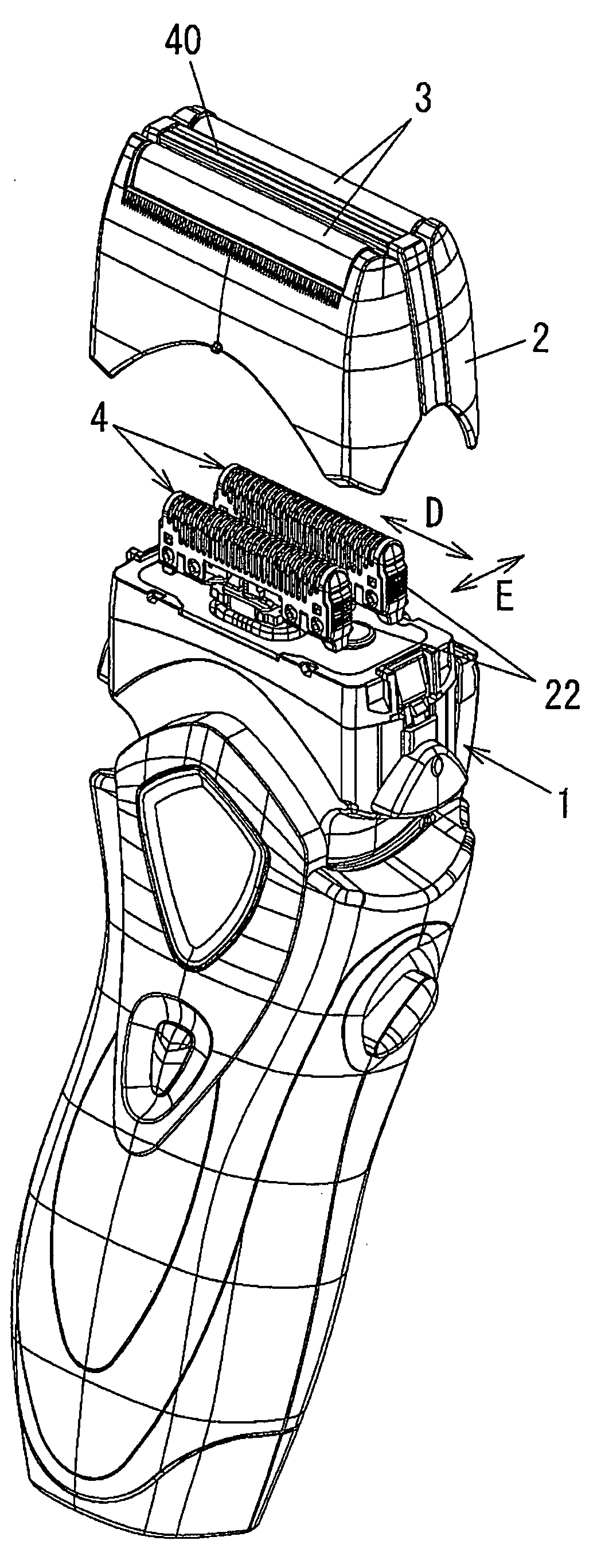
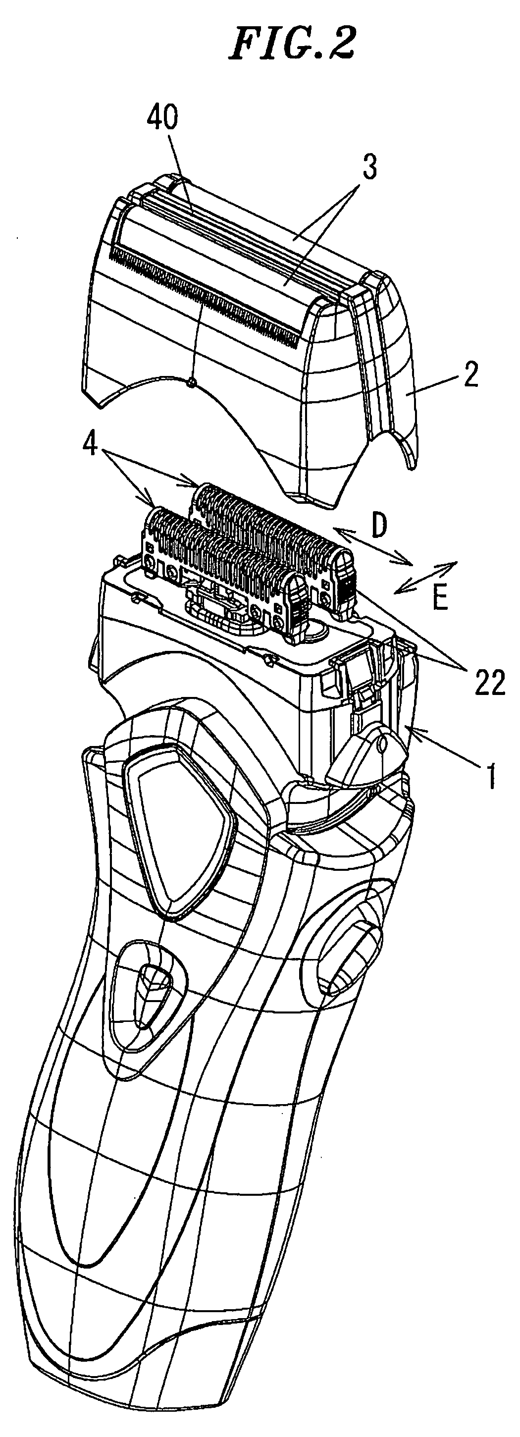
[0034]FIG. 2 shows a reciprocating type electric shaver in accordance with an embodiment of the present invention. The electric shaver of this embodiment includes a main body 1 accommodating therein a motor (not shown); an outer blade cassette 2 to be connected with an upper rim of the main body 1; a pair of net-shaped outer blades 3 and a center blade 40, all being provided at a top opening of the outer blade cassette 2; and a pair of inner blade member 4 disposed at inner sides of the outer blades 3 and detachably connected at the main body 1.

[0035]As illustrated in FIG. 3, a pair of driving units 7 are disposed protruding from an upper portion of the main body 1. When the pair of inner blade member 4 (see FIG. 2) detachably attached to the driving units 7 move reciprocally as a unit with the driving units 7, hair (beard) introduced through apertures of t...


PUM


Abstract

An electric shaver includes net-shaped outer blades; and inner blades sliding reciprocally over an inner side of the outer blades as detachably connected with driving units driven by a motor. Each of the inner blades includes a blade plate having an inversed-like-U shape seen from a longitudinal direction in parallel with a reciprocating sliding direction; and a blade holder having attaching portions to be attached to the blade plate in longitudinally defined end regions, wherein connection portions to be detachably connected with the driving units are provided at the blade holder in a longitudinally defined center region, and, when dissembling the blade holder from the driving units, anti-detach portions are provided to thereby prevent separation of the blade holder in the longitudinally defined center region from the blade plate in the longitudinally defined center region due to a tensile load between the connection portions and the driving units.

Description

FIELD OF THE INVENTION[0001]The present invention relates to an electric shaver having an inner blade member sliding reciprocally over an inner side of an outer blade; and, more particularly, to an inner blade member which is configured to prevent deformation of a blade holder of an inner blade in a longitudinally defined central region, the deformation being caused when assembling / dissembling the inner blade member to / from a driving unit to be driven by a motor.BACKGROUND OF THE INVENTION[0002]In general, a reciprocating type electric shaver includes a main body; an outer blade cassette connected with an upper portion of the main body; a net-shaped outer blade disposed at an upper portion of the outer blade cassette; and an inner blade member sliding reciprocally over an inner side of the outer blade, the inner blade being driven while being connected with the main body. Hair (beard) introduced through apertures of the outer blade is cut by reciprocal motion of blades of the inner ...

Claims


Application Information

Patent Timeline
Patent Type & Authority Applications(United States)
IPC IPC(8): B26B19/04
CPCB26B19/044B26B19/04B26B19/12B26B19/38
Inventor SATO, MASAAKIKOMORI, SHUNSUKESHIBA, TAKESHIIWASAKI, JYUZAEMON
Owner MATSUSHITA ELECTRIC WORKS LTD
Why Eureka
Try Eureka