Truss and rafter tide guide

a technology of trusses and rafters, applied in the field of tie guides, can solve the problems of large construction problems, severe alignment problems along the cross member, and increase the complexity of the guide, and achieve the effect of simple manufacturing and shipping, and great strength

Active Publication Date: 2008-01-24
WALKER MICHAEL
View PDF43 Cites 4 Cited by
  • Summary
  • Abstract
  • Description
  • Claims
  • Application Information

AI Technical Summary

Benefits of technology

[0012]An advantage of the present invention is that the guide provides for the simple placement of cross members on a support wall and has support on the horizontal surface of the support wall as well as the vertical surface of the wall. Further, the guide provides for a large number of fasteners to affix the plate and the fixing members to the support wall and cross member, respectively, for greatly increased strength. Even further, the guide is simple to manufacture and ship.
is that the guide provides for the simple placement of cross members on a support wall and has support on the horizontal surface of the support wall as well as the vertical surface of the wall. Further, the guide provides for a large number of fasteners to affix the plate and the fixing members to the support wall and cross member, respectively, for greatly increased strength. Even further, the guide is simple to manufacture and ship.

Problems solved by technology

Even small errors in the measurement tend to accumulate and cause large problems in the construction.
These errors may cause severe alignment issues along the cross member from one support wall to the next.
Brackets may be used to hold the cross member in position; however, such brackets provide for few fasteners for supporting the member.
Jones's fixing members include flanges; however, they add to the complexity of the guide and require additional steps in manufacturing.
Further, Jones's mounting devices are affixed to the top of the support wall only, with no way to attach to the vertical portion of the support wall.
Further, Weller's truss guide is mounted to the top of the support structure with no way to attach to the vertical portion of the support wall.

Method used


Image

  • Truss and rafter tide guide
  • Truss and rafter tide guide
  • Truss and rafter tide guide

Examples


Embodiment Construction

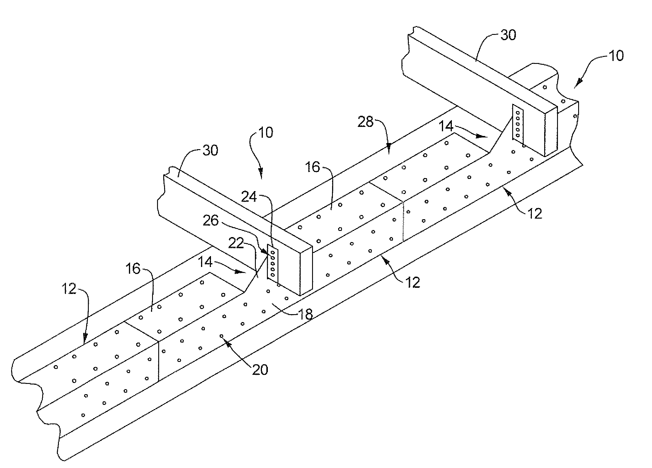
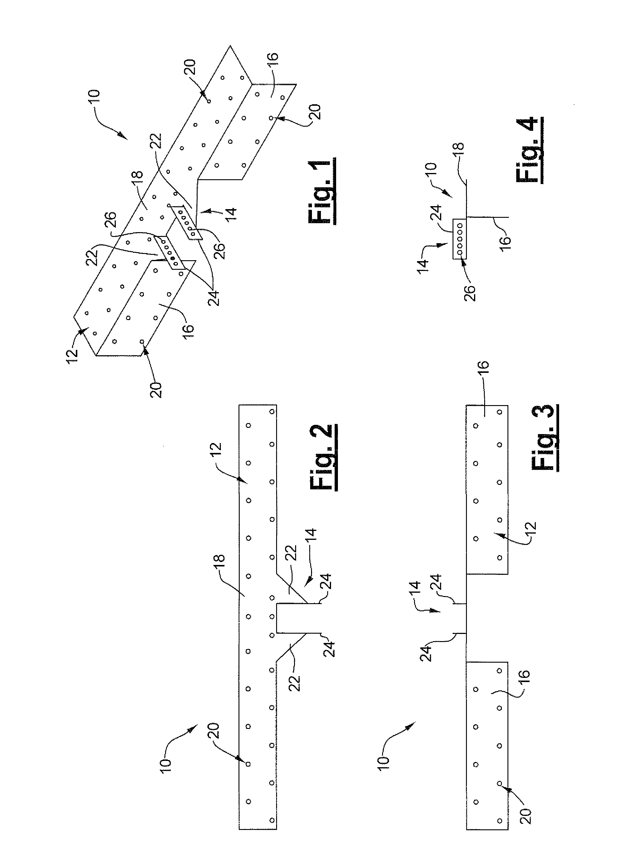
[0022]Referring to FIGS. 1-4, there is shown the truss / rafter guide of the present invention. The guide 10 is made of sheet metal or other suitable material and includes a support plate 12 and a bracket 14. The support plate 12 includes horizontal flanges 16 and an elongate vertical flange 18. A number of spaced-apart holes 20 in the support plate 12 are each sized for a clearance fit with a fastener, such as a nail or a screw, for securing the plate 12 to the top of a support wall.

[0023]The bracket 14 includes a pair of sloped flanges 22 extending vertically from the vertical flange 18. The flanges 22 each support a substantially planar fixing member 24 that includes a plurality of holes 26, each sized for a clearance fit with a fastener, such as a nail or a screw, for securing the fixing members 24 to a cross member.

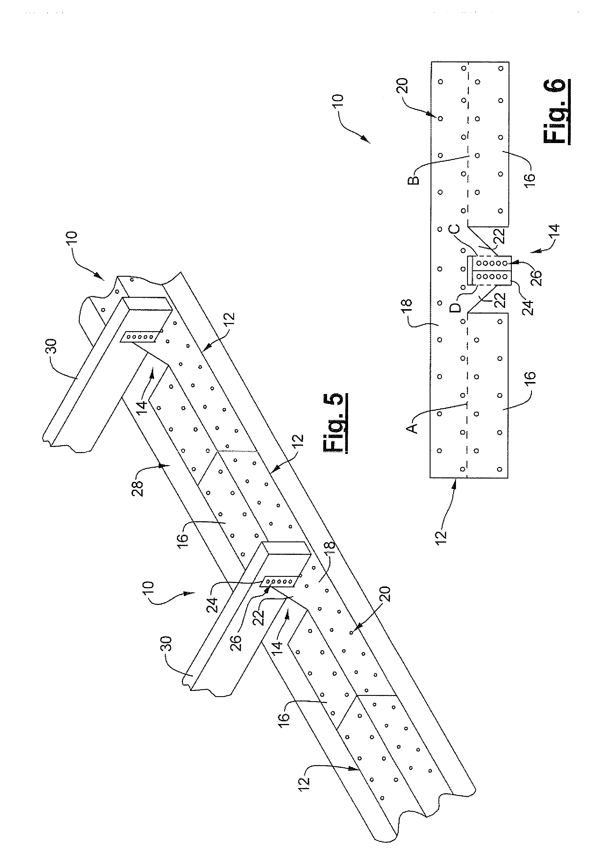
[0024]The guide 10 is affixed to a support wall and cross member as shown in FIG. 5. The support plate 12 is placed over the edge of the top of the support wall 28 and...


PUM


Abstract

The invention provides tie guides for affixing trusses and rafters and other cross members to the supporting walls of a building. The tie guide includes a longitudinal base plate with a horizontal component and a vertical component. Fixing members are transverse to the base plate, and are supported by triangular flanges extending in the longitudinal direction.

Description

CROSS-REFERENCE TO RELATED APPLICATIONS[0001]This application claims priority from U.S. Provisional Patent Application Ser. No. 60 / 795,016, filed Apr. 25, 2006, which is herein incorporated by reference.FIELD OF THE INVENTION[0002]This invention relates tie guides for affixing trusses and rafters to the supporting walls of a building.BACKGROUND OF THE INVENTION[0003]In building a structure such as a house or a shed, it is important to ensure the proper spacing of joists, trusses, rafters, or beams when affixing them to the support walls. This requires careful measurement during construction such that the centers of the cross members are spaced according to the specified dimension. For example the spacing of the cross members is generally 12, 16, or 24 inches, though other distances may be specified. Even small errors in the measurement tend to accumulate and cause large problems in the construction. Also, the cross member may move when attaching it to the support wall. These errors ...

Claims


Application Information

Patent Timeline
Patent Type & Authority Applications(United States)
IPC IPC(8): E04B7/04
CPCY10T403/73E04B7/045F16B2200/67
Inventor WALKER, MICHAEL
Owner WALKER MICHAEL
Why Eureka
Try Eureka