
High efficiency HVAC filter

a hvac filter and high efficiency technology, applied in the direction of filtration separation, separation process, transportation and packaging, etc., can solve the problems of equipment failure or injury to users and workers, unsuitable longer-term applications, and generally is not possible, and achieve the effect of small particle efficiency and low basis weigh

Inactive Publication Date: 2008-01-24
3M INNOVATIVE PROPERTIES CO
View PDF37 Cites 86 Cited by
  • Summary
  • Abstract
  • Description
  • Claims
  • Application Information

AI Technical Summary

Benefits of technology

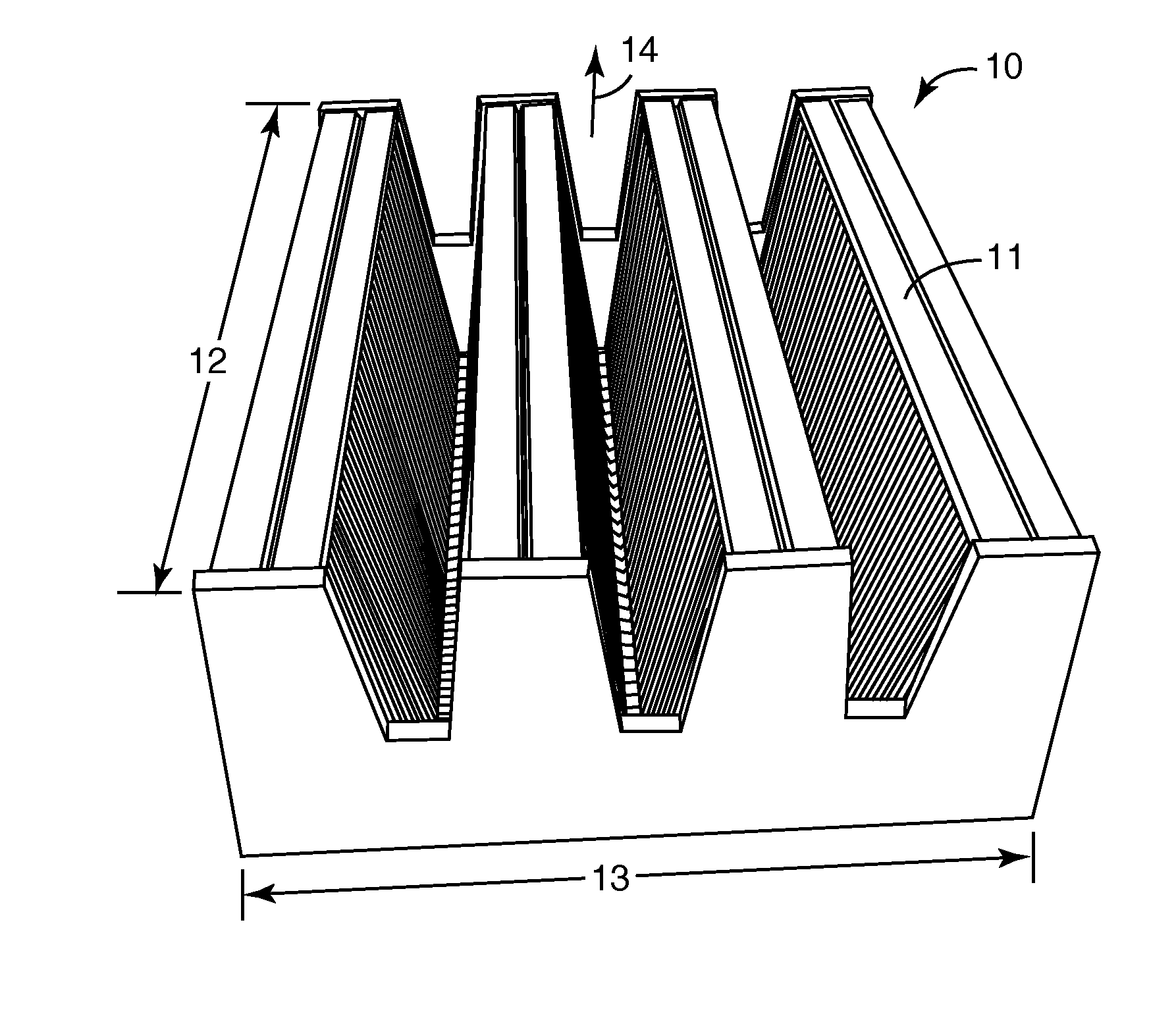
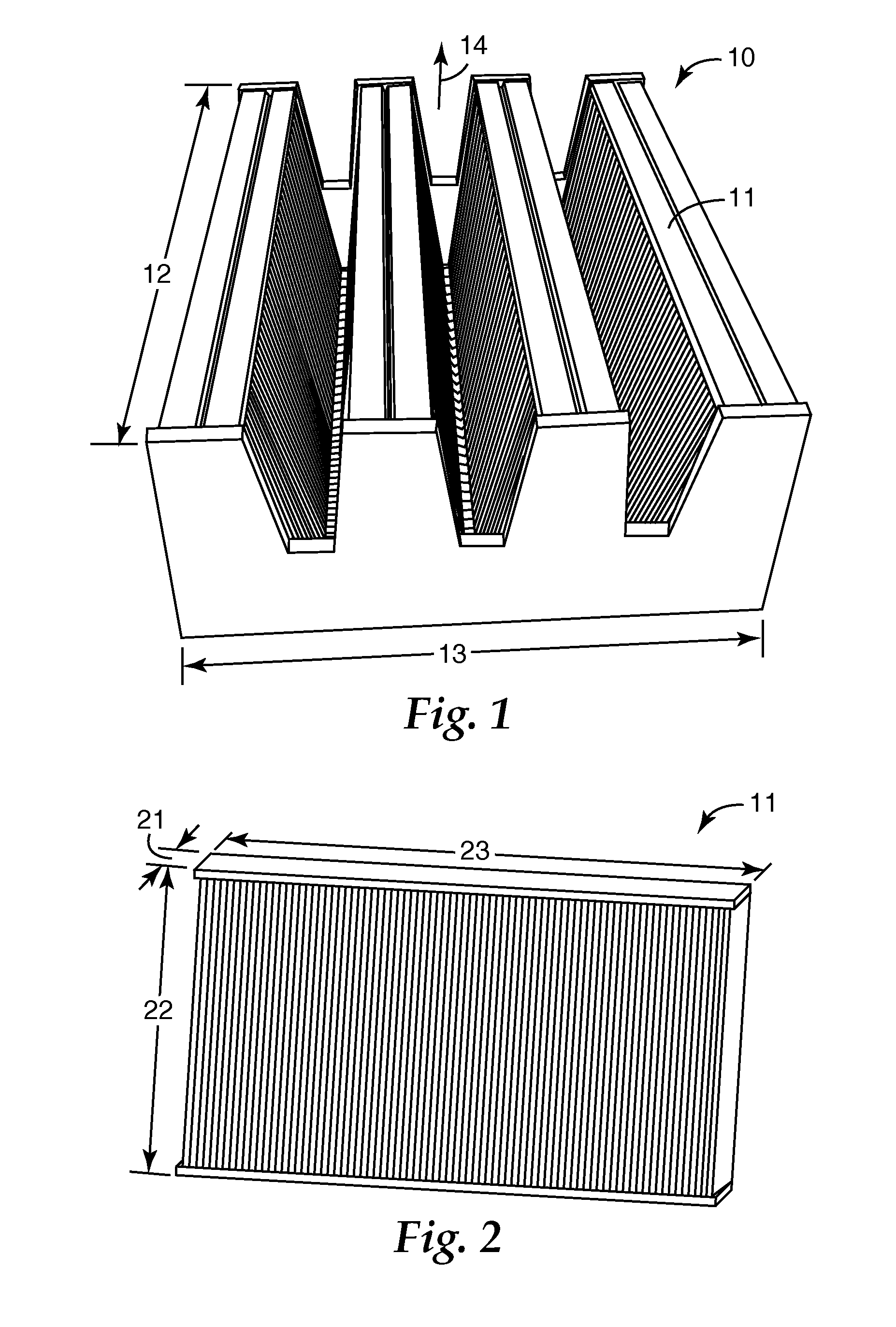
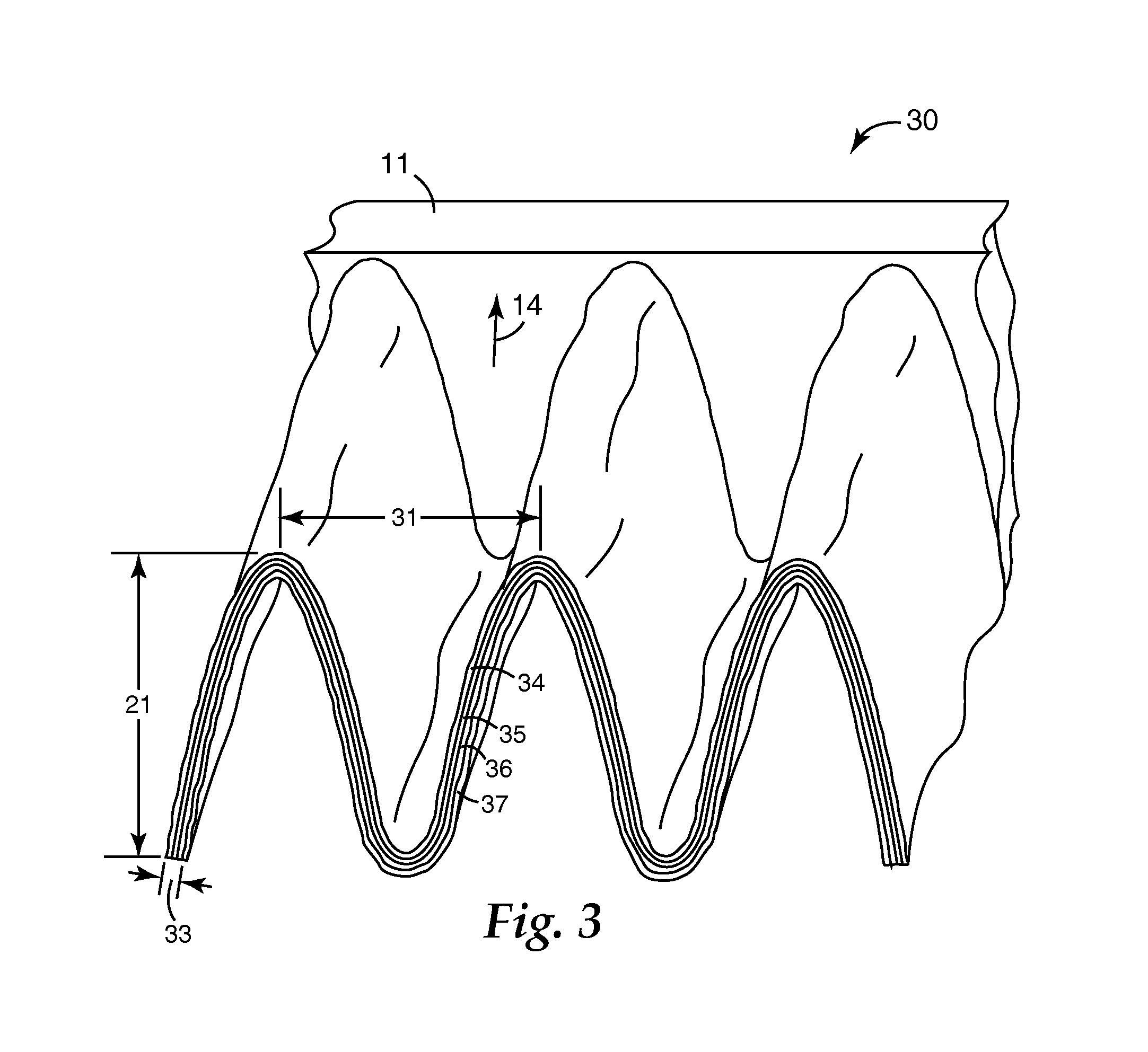
[0006]The invention is a pleated HVAC filter containing a pleated filter media laminate of a melt blown nonwoven media containing layer and a nanofiber filter media layer. The melt blown nonwoven media containing layer has an upstream face and a downstream face, where the downstream face is laminated to the nanofiber filter media layer. The melt blown nonwoven media further has a very low basis weight of less than 30 grams/m2 and a thickness of less than 1 mm, the filter media laminate, which includes supporting scrim layers, has a b...

Problems solved by technology

In other instances, such as production gases or off gases from industrial processes or engines particle removal is desired but pressure drop is of a higher priority as high backpressure on pumps and other equipment could lead to equipment failure or injury to users and workers.
With surface loading filters this generally is not possible unless the filter media is able to be periodically cleaned such as by backpulsing.
With depth loading filters to obtain the necessary efficiencies it is often desired to charge the filter media, however charges will dissipate or be shielded over time making this solution often unsuitable for longer term applications such as those required for high efficiency filters (for example, MERV 12 and MERV 14 applications per ASHRAE Standard 52.2-1999).
With these uses frequent filter changeout is costly and / or sometimes missed.

Method used


Image

  • High efficiency HVAC filter
  • High efficiency HVAC filter
  • High efficiency HVAC filter

Examples


examples

[0027]Preparation of the Filter Media Laminate Materials

Filter Laminate 1 (Hereinafter Below “Web”)

Web Preparation

[0028]A polypropylene based melt blown microfiber (BMF) web was prepared using a melt blowing process similar to that described, for example, in Wente, “Superfine Thermoplastic Fibers,” in Industrial Engineering Chemistry, Vol. 48, pages 1342 et seq (1956) or in Report No. 4364 of the Naval Research Laboratories, published May 25, 1954, entitled “Manufacture of Superfine Organic Fibers” by Wente et al. The extruder had ten temperature control zones that were maintained at 400° F. (204° C.), 450° F. (232° C.), 500° F. (260° C.), 540° F. (282° C.), 575° F. (302° C.), 610° F. (321° C.), 640° F. (338° C.), 665° F. (352° C.), 685° F. (363° C.) and 695° F. (368° C.), respectively. The flow tube connecting the extruder to the die was maintained at 575° F. (302° C.), and the BMF die was maintained at 600° F. (316° C.). The primary air was maintained at about 660° F. (349° C.), a...


PUM

PropertyMeasurementUnit
Lengthaaaaaaaaaa
Lengthaaaaaaaaaa
Lengthaaaaaaaaaa

Abstract

There is provided a pleated HVAC type filter containing a pleated filter media laminate of a melt blown nonwoven media containing layer and a nanofiber filter media layer. The melt blown nonwoven media containing layer has an upstream face and a downstream face, where the downstream face is laminated to the nanofiber filter media layer. The melt blown nonwoven media further has a very low basis weight of less than 30 grams / m2 and a thickness of less than 1 mm, the filter media laminate, which includes supporting scrim layers, has a basis weight of less than 200 grams / m2 and a thickness of less than 3 mm where the filter media laminate is pleated to a pleat density of at least 1 pleats / cm and has an initial pressure drop of less than 0.45 inches of water, a small particle efficiency, relative to 0.3 to 1.0 micron particles, of greater than 70 percent, the nanofiber filter media comprising a nanofiber web on a support backing, wherein the nanofibers have a diameter of less than 1.0 microns and an efficiency relative to 0.8 micron PSL particles of greater than 30 percent.

Description

BACKGROUND AND FIELD OF THE INVENTION[0001]The present invention relates to high efficiency particulate HVAC filters.[0002]The removal of some or all of the particulate material from air and gas streams over extended time periods is an often addressed need. For example, air intake streams to the cabins of motorized vehicles, air in computer disk drives, HVAC air, aircraft cabin ventilation, clean room ventilation, air to engines for motorized vehicles, or to power generation equipment; gas streams directed to gas turbines; and, air streams to various combustion furnaces, often include particulate material that needs to be constantly filtered or otherwise removed. All these applications and others not listed have very different particle removal needs, priorities and requirements. In the case of cabin air filters it is desirable to remove the particulate matter for comfort of the passengers and / or for aesthetics. In clean rooms extremely high particle removal is needed, often regardle...

Claims


Application Information

Patent Timeline
IPC IPC(8): B01D53/04
CPCB01D39/1623B01D46/125B01D46/521B01D2239/025B32B27/32B01D2239/0681B32B5/26B32B27/02B32B27/12B01D2239/0668B01D46/121B01D46/10B01D39/00B82Y30/00
Inventor WU, TIEN T.
Owner 3M INNOVATIVE PROPERTIES CO
Learn More