Woven Shutter

Inactive Publication Date: 2008-01-24
CHEN CHIN FU
View PDF7 Cites 6 Cited by
  • Summary
  • Abstract
  • Description
  • Claims
  • Application Information

AI Technical Summary

Benefits of technology

[0004]The primary objective of the present invention is to overcome the foregoing shortcomings and avoid the existing deficiencies by providing a woven shutter that comprises a metal upper rail, and the shutter has a first blind fixed to a side of the upper rail, and a movable and foldable second blind disposed on another side of the shutter. The first and second blinds include a first edge bar and a second edge bar disposed adjacen

Problems solved by technology

Since the plastic panels 5 have a specific thickness without

Method used


Image

  • Woven Shutter
  • Woven Shutter
  • Woven Shutter

Examples


Embodiment Construction

[0010]To make it easier for our examiner to understand the technical characteristics, objective and performance of the invention, we use a preferred embodiment together with the attached drawings for the detailed description of the invention.

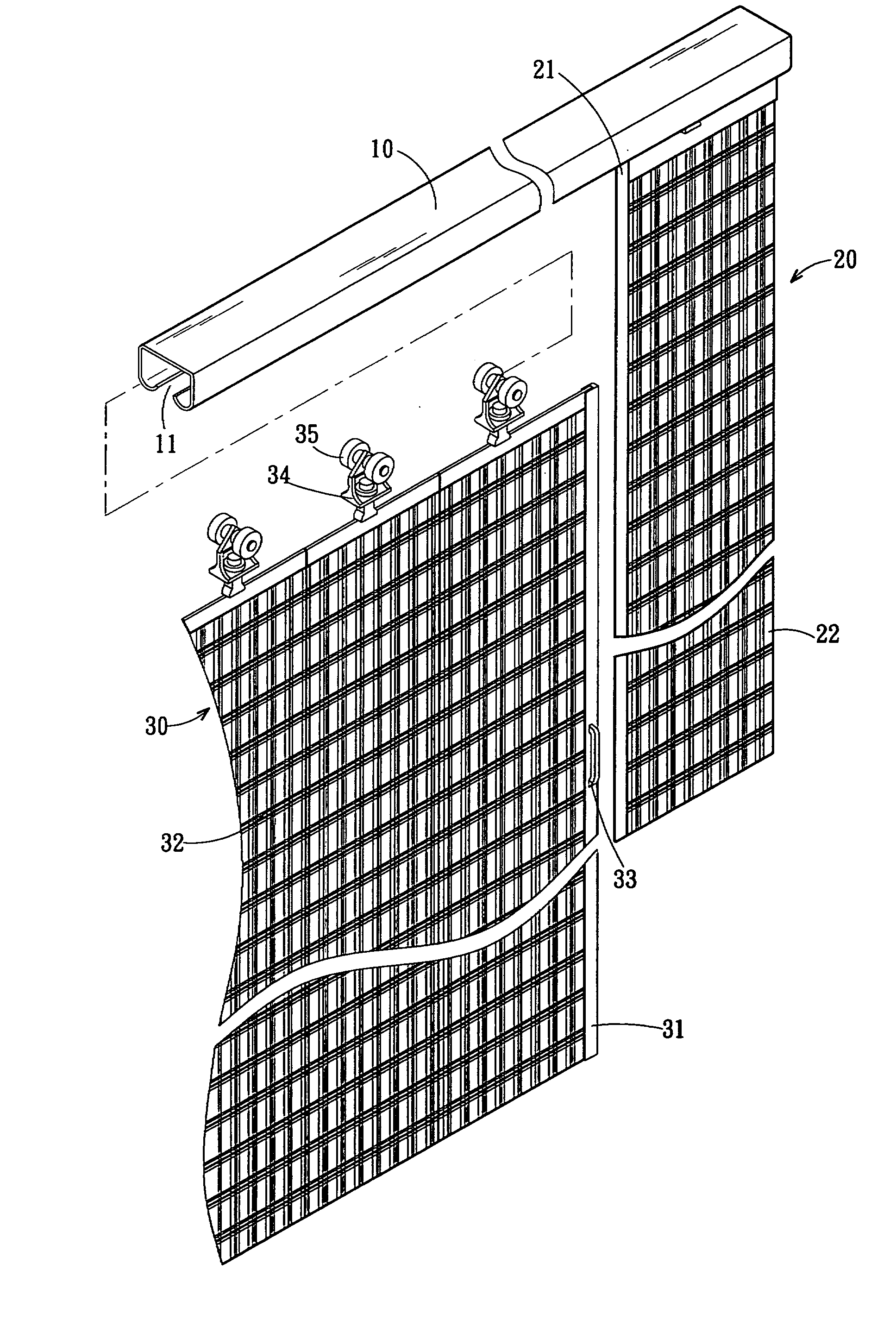
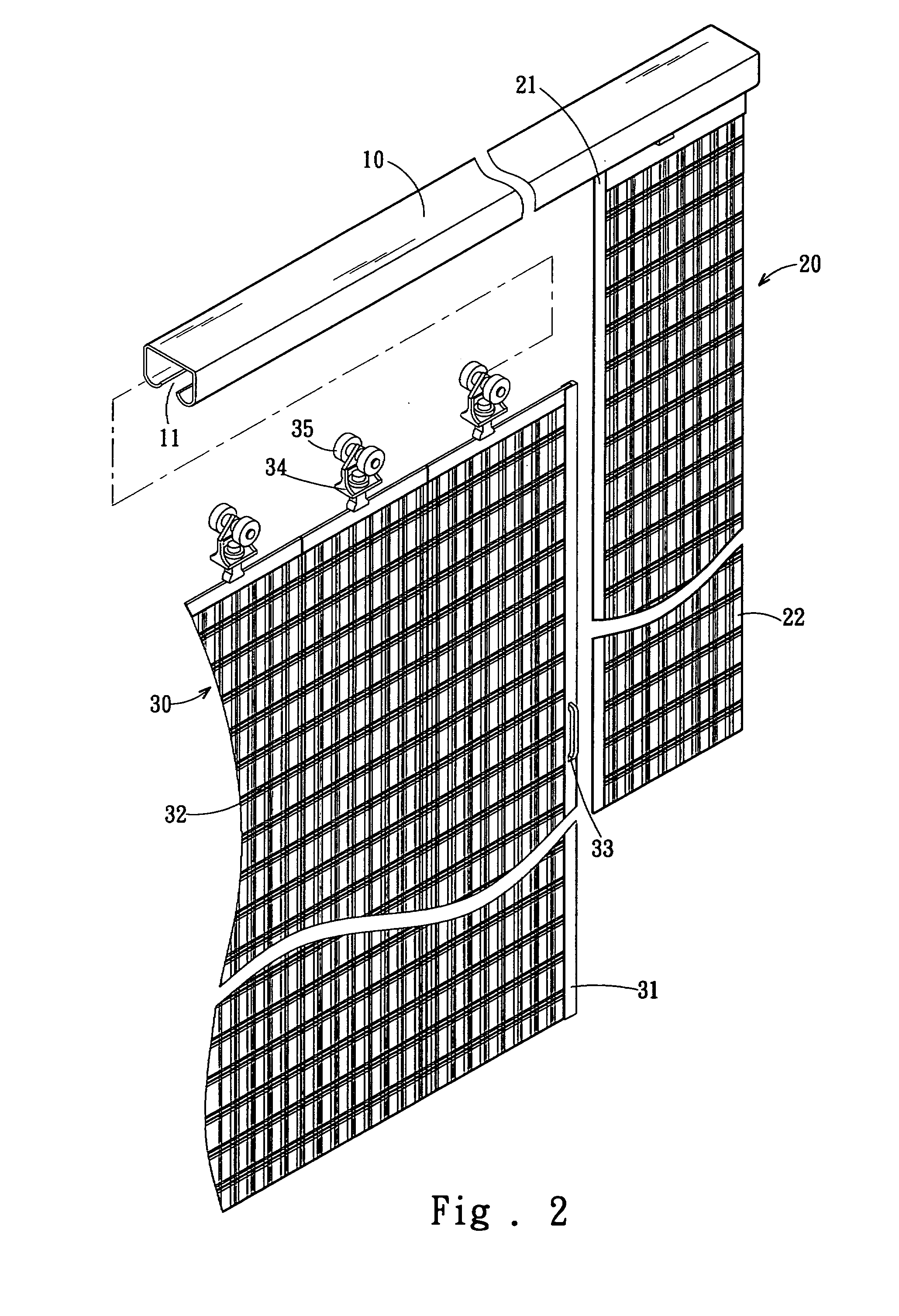
[0011]Referring FIG. 2, a woven shutter comprises the following elements:

[0012]A metal upper rail 10 is a rectangular hollow body and has an opening 11 disposed under the upper rail 10, and the width of the opening 11 is smaller than the internal width of the upper rail 10. A fixed vertical plastic first blind 20 has its top fixed to a side of the bottom of the upper rail 10, and the external side of the first blind 20 can be fixed onto a wall surface (not shown in the figure), and the internal side of the first blind 20 has a vertical first edge bar 21, and the first blind 20 is made of a sheet body 22, and the sheet body 22 and transversally woven materials form a rectangular surface with woven lines as shown in FIG. 3.

[0013]A movable and fold...


PUM


Abstract

The present invention discloses a woven shutter that includes an upper rail, and the shutter has a fixed first blind fixed to a side of the upper rail and a foldable second blind movably disposed on another side of the upper rail. The first blind and the second blind have a first edge bar and a second edge bar disposed adjacent to the edges of first and second blinds respectively, and the second edge bar of the second blind has a handle, and the first and second blinds are made of a plurality of vertical sheet bodies, and each sheet body is made of longitudinally and transversally woven materials, so as to provide a shutter with the effects of ventilation, light weight and variable lines.

Description

FIELD OF THE INVENTION[0001]The present invention relates to a foldable shutter, and more particularly to a shutter structure having woven lines to provide a variable three-dimensional effect.BACKGROUND OF THE INVENTION[0002]Referring to FIG. 1 for a common foldable shutter available in the market, the shutter includes a metal upper rail 1 fixed to a ceiling, and the upper rail 1 is a rectangular hollow body containing a slider 2, and rollers 3 disposed on both sides of the slider 2 can be moved sideway in the upper rail 1. A channel 4 is disposed under the hollow body of the upper rail 1, and a plurality of hard plastic panels 5 are disposed under the upper rail 1, and a hanger 6 is disposed at the top of each plastic panel 5 and connected to the slider 2, and a soft plastic film 7 is disposed between the plastic panels 5, such that each plastic panel 5 can be folded, and thus users can simply pull the outermost plastic panel 5 by hands to spread each plastic panel 5 to form a shee...

Claims


Application Information

Patent Timeline
IPC IPC(8): A47H1/00
CPCA47H15/02E06B9/36A47H2023/025A47H23/08
Inventor CHEN, CHIN-FU
Owner CHEN CHIN FU
Why Eureka
Try Eureka