Particulate loading monitoring system

a technology of monitoring system and trap, applied in the direction of machine/engine, exhaust treatment electric control, transportation and packaging, etc., can solve the problems of system components that are more complicated, damage to filters and/or engine performance decline, and cost more at each stage of development and production

Inactive Publication Date: 2008-01-24
KNITT ANDREW A
View PDF8 Cites 33 Cited by
  • Summary
  • Abstract
  • Description
  • Claims
  • Application Information

AI Technical Summary

Problems solved by technology

The use of the particulate trap for extended periods of time, however, may enable particulate matter to accumulate on the filter, thereby causing damage to the filter and / or a decline in engine performance.
However, the system of the '771 patent utilizes microwaves rather than low frequency RF signals.
Use of higher frequencies, such as the microwaves used in the '771 patent, requires system components that are more complicated and thus cost more at each stage of development and production.
The requirement of such a chamber may limit the design possibilities of a particulate trap housing.

Method used


Image

  • Particulate loading monitoring system
  • Particulate loading monitoring system
  • Particulate loading monitoring system

Examples


Embodiment Construction

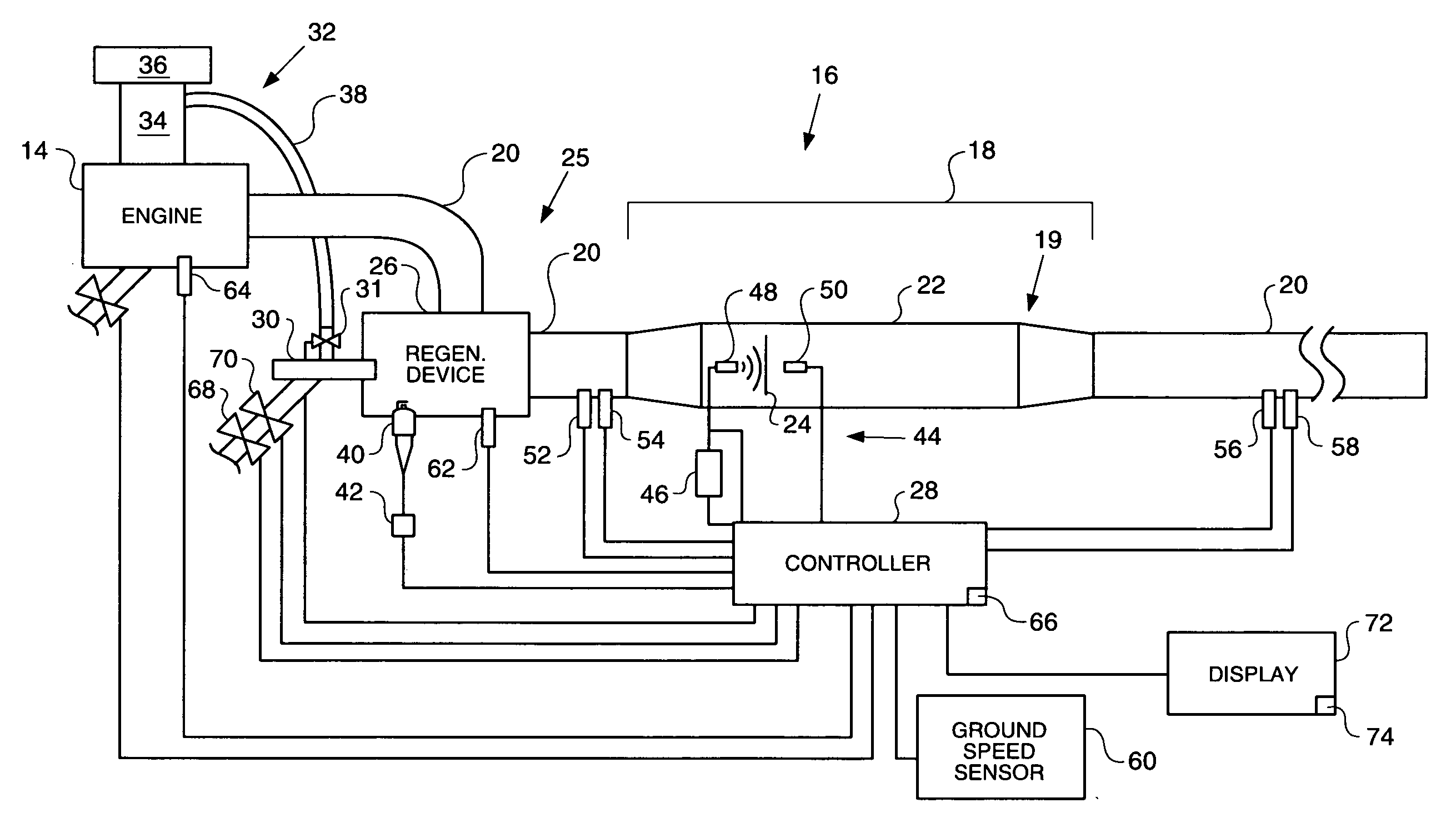
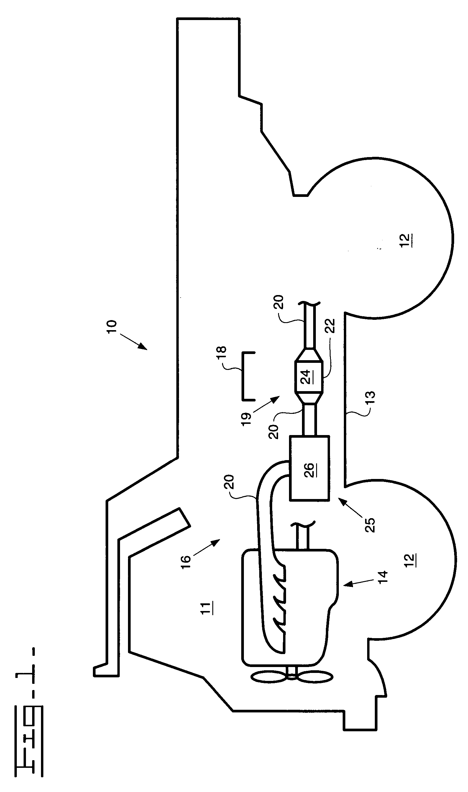
[0021] Reference will now be made in detail to embodiments of the invention, examples of which are illustrated in the accompanying drawings. Whenever possible, the same reference numbers will be used throughout the drawings to refer to the same or like parts.

[0022]FIG. 1 illustrates a machine 10. Machine 10 may include an operator station 11, one or more traction devices 12, a frame 13, an engine 14, which may be mounted to frame 13, and a particulate trap regeneration system 16.

[0023] Although machine 10 is shown as a truck, machine 10 could be any type of machine having an exhaust producing engine. Accordingly, traction devices 12 may be any type of traction devices, such as, for example, wheels, as shown in FIG. 1, tracks, belts, or any combinations thereof.

[0024] Engine 14 may be any kind of engine that produces an exhaust flow of exhaust gases. For example, engine 14 may be an internal combustion engine, such as a gasoline engine, a diesel engine, a gaseous fuel burning engi...


PUM


Abstract

A particulate trap regeneration system is provided, which may include a particulate trap having a filter medium configured to remove one or more types of particulate matter from an exhaust flow of an engine and a regeneration device configured to reduce an amount of particulate matter in the particulate trap, as well as a radio frequency-based particulate loading monitoring system configured to determine an amount of particulate matter trapped by the filter medium. The particulate loading monitoring system may include at least one radio frequency reader located along the exhaust conduit and outside the particulate trap configured to transmit a first radio frequency signals within the exhaust conduit and at least one radio frequency probe configured to receive the first radio frequency signal and responsively transmit a second radio frequency signal readable by the radio frequency reader.

Description

RELATED APPLICATIONS [0001] This application is a continuation of U.S. patent application Ser. No. 11 / 644,540, filed Dec. 21, 2006, which is a continuation-in-part of U.S. patent application Ser. No. 11 / 393681, filed Mar. 31, 2006, which is a continuation-in-part of U.S. patent application Ser. No, 11 / 189530, filed Jul. 26, 2005.TECHNICAL FIELD [0002] The present disclosure is directed to a particulate trap regeneration system and, more particularly, to a particulate trap regeneration system having a particulate loading monitoring system. BACKGROUND [0003] Engines, including diesel engines, gasoline engines, natural gas engines, and other engines known in the art, may exhaust a complex mixture of air pollutants. The air pollutants may be composed of both gaseous and solid material, such as, for example, particulate matter. Particulate matter may include ash and unburned carbon particles and may sometimes be referred to as soot. [0004] Due to increased environmental concerns, exhaust...

Claims


Application Information

Patent Timeline
Patent Type & Authority Applications(United States)
IPC IPC(8): B60Q1/00
CPCF01N3/025F01N9/002F01N2560/00Y02T10/47F01N2560/08F01N2560/14F02D2200/0812F01N2560/06Y02T10/40
Inventor KNITT, ANDREW A.
Owner KNITT ANDREW A
Why Eureka
Try Eureka