System and method for correcting for ring artifacts in an image

a technology of image data and artifact correction, applied in image enhancement, instruments, therapy, etc., can solve the problems of ring artifacts, ring artifacts, and mechanical instabilities of rotatable gantry that can produce elliptical rather than circular artifacts

Active Publication Date: 2008-01-24
VARIAN MEDICAL SYSTEMS
View PDF17 Cites 27 Cited by
  • Summary
  • Abstract
  • Description
  • Claims
  • Application Information

AI Technical Summary

Benefits of technology

[0011]In one example of an embodiment of the invention, a method to correct for ring artifacts in an image is disclosed, comprising reconstructing a first Cartesian image based on data received from an imaging device, in Cartesian coordinates, and transforming the first Cartesian image into a first polar image in polar coordinates. The method further comprises applying a first low-pass filter to the first polar image, in the radial dimension, to form a second polar image, and subtracting the second polar image from the first polar image to form a third polar image. The method additionally comprises applying a second low-pass filter to the third polar image, in the angular dimension, to form a fourth polar image, and transforming the fourth polar image to Cartesian coordinates to form a second Cartesian image. The first Car...

Problems solved by technology

One problem with third generation CT scanning is the occasional appearance of circular or elliptical ring artifacts in the output image.
Ring artifacts may be caused by one or more faulty detectors that produce varying signal outputs.
In addition, mechanical instabilities of the rotatable gantry can produce elliptical rather than circular artifacts.
Physical characteristics of the imaging apparatus and/or detector can also cause variable intensity and/or partial ring artifacts (semi-circular, for example).
Artifacts can degrade image...

Method used


Image

  • System and method for correcting for ring artifacts in an image
  • System and method for correcting for ring artifacts in an image
  • System and method for correcting for ring artifacts in an image

Examples


Embodiment Construction

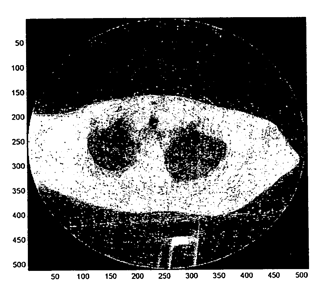
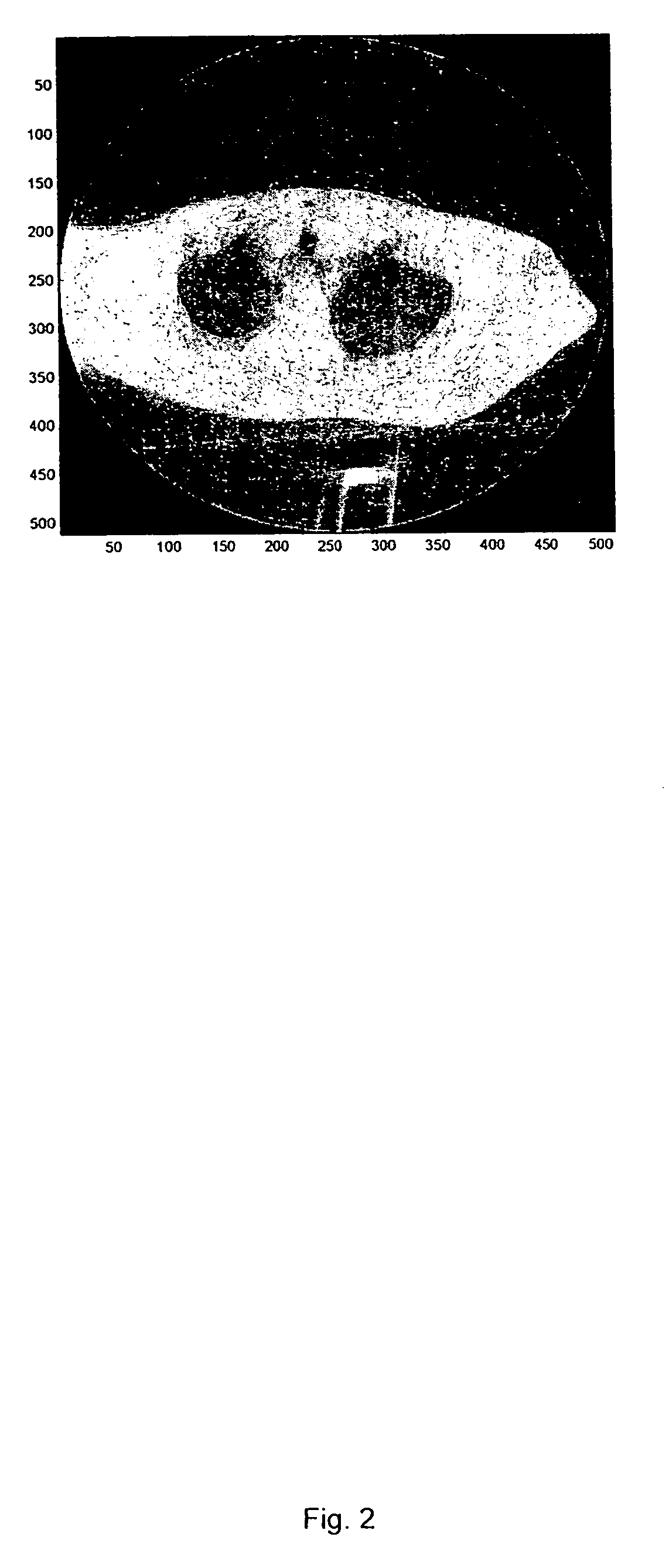
[0035]In one example of an embodiment of the invention, an image generated by third generation CT scanning is examined and processed by a computer to correct for ring artifacts in the image. In this example, raw CT data is reconstructed into an image in Cartesian coordinates. The Cartesian image is transformed into an image in polar coordinates. Polar ring artifacts are identified in the polar image, and the identified polar ring artifacts are filtered. The Cartesian image is then corrected based, at least in part, on the filtered polar ring artifacts. To filter the polar ring artifacts, in one example, a row-based low-pass filter is applied to the polar image to generate a local median value matrix, which is subtracted from the polar image to generate a polar image of the ring artifacts. A column-based low-pass filter is then applied to the polar image. In one example, the row and column filtered polar image, which is in polar coordinates, is transformed into Cartesian coordinates,...


PUM


Abstract

In one example of an embodiment of the invention, a method to correct for ring artifacts in an image is disclosed. A first Cartesian image is reconstructed based on data received from an imaging device, and the first Cartesian image is transformed into a first polar image. A first low-pass filter is applied to the first polar image, in the radial dimension, to form a second polar image, and the second polar image is subtracted from the first polar image to generate a third polar image. A second low-pass filter is applied to the third polar image, in an angular dimension, to form a fourth polar image, and the fourth polar image is transformed to Cartesian coordinates to form a second Cartesian image. The first Cartesian image is corrected based, at least in part, on the second Cartesian image.

Description

FIELD OF THE INVENTION[0001]This invention relates generally to a system and method for reducing artifacts in image data. More particularly, this invention relates to a system and method for identifying and mitigating ring artifacts in image data obtained by computed tomography (CT).BACKGROUND OF THE INVENTION [0002]Computed tomography (“CT”) scanning enables a doctor to obtain detailed images of a patient's internal organs and tissues. CT scanning is used in a variety of medical fields, such as in radiology, cardiology and oncology, to diagnosis conditions and diseases, as well as to plan radiation treatments, for example. CT scanning has also been used in other fields to identify defects in machinery, to perform baggage inspections at airports, and to analyze the internal anatomy of preserved Egyptian mummies, for example.[0003]To obtain a CT image, a portion of a patient or other such target is irradiated by X-ray radiation at a sufficient number of angles to enable CT image reco...

Claims


Application Information

Patent Timeline
IPC IPC(8): G06K9/40
CPCA61N5/1049A61N2005/1061G06T2207/20032G06T2207/10081G06T5/002G06T5/50
Inventor STAR-LACK, JOSHMOSTAFAVI, HASSANPAVKOVICH, JOHN
Owner VARIAN MEDICAL SYSTEMS
Why Eureka
Try Eureka