Intersomatic cage with unified grafts

a technology of intersomatic cage and graft, which is applied in the field of intervertebral cage, can solve problems such as complicated cages, and achieve the effects of increasing air gap, avoiding endangering stability and strength, and being more resistant to tension forces

Inactive Publication Date: 2008-01-24
LDR MEDICAL SAS
View PDF6 Cites 37 Cited by
  • Summary
  • Abstract
  • Description
  • Claims
  • Application Information

AI Technical Summary

Benefits of technology

[0009] The present invention overcomes the disadvantages mentioned above by proposing an intervertebral cage that enables good growth of the graft or grafts placed between the vertebrae and is each to make, particularly due to the fact that it has straight longitudinal walls, and has good resistance to compression forces applied by the vertebral plates, particularly in the case of posterior implantation in which two intervertebral cages are placed side by side at a distance from each other.
[0011] Thus, according to the invention, the intervertebral cage comprises only three walls, namely the straight main wall and the two return parts prolonged by the end parts, such that the graft was compacted on the inside of each cage before the cage was placed (in the case of posterior placement in which two cages are used arranged side by side and at a spacing from each other), and the graft that is made to grow between the two cages are all three in mutual contact, such that there is actually only a single graft which will therefore grow homogeneously to obtain an optimum contact between the vertebral plate—graft—vertebral plate, in other words a good homogeneous and stable contact, also making the cage more resistant even though it only has one straight main wall and a large gap between the end parts.
[0012] The applicant realized before anyone else that in the case in which there is a main part in the form of a straight wall, it is still possible to significantly move the end parts away from the return parts without endangering the stability and the strength of the intervertebral cages between the vertebral plates. The applicant believes that the fact that the central graft and the compacted grafts in the internal parts of the two cages arranged with their openings facing each other fuse together well and helps to make the two cages more resistant to the tension forces exerted by the vertebral plates, and it is therefore possible to increase the air gap between the end parts, although the main part is only a thin single straight wall; but this is only a hypothesis that the applicant cannot confirm.
[0020] The rectangular wall replaces the “missing wall” of the cage during placement, firstly to retain the graft that was compacted inside the cage before the cage was put into position, and secondly to make the assembly stiffer to facilitate its placement in the intervertebral space.

Problems solved by technology

Obviously, this is a disadvantage, particularly with regard to the stability of the grafts and the two vertebrae held in place by these grafts, and concerning the time necessary to obtain good stability.
Therefore, these cages are complicated to make due to their curved shape.

Method used


Image

  • Intersomatic cage with unified grafts
  • Intersomatic cage with unified grafts
  • Intersomatic cage with unified grafts

Examples


Embodiment Construction

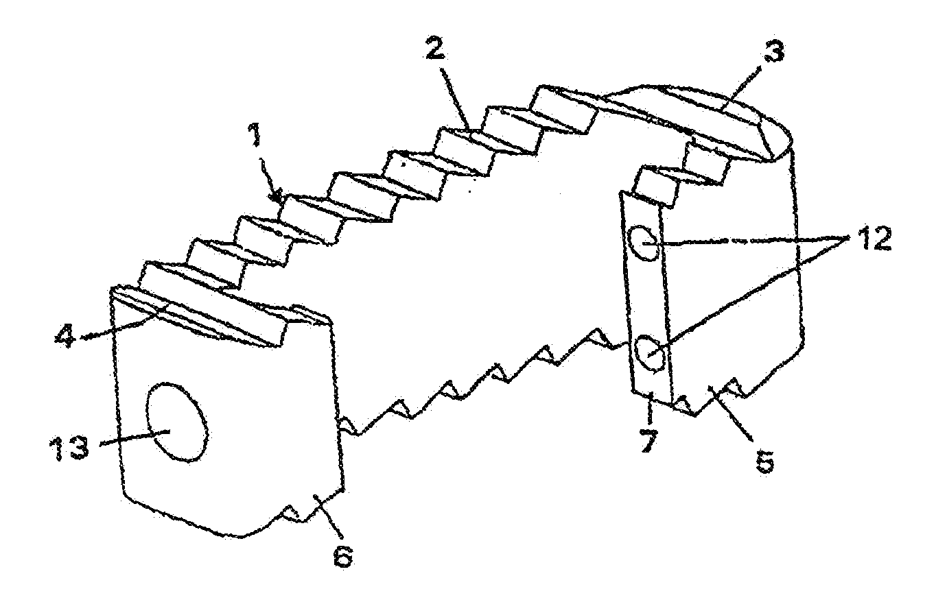
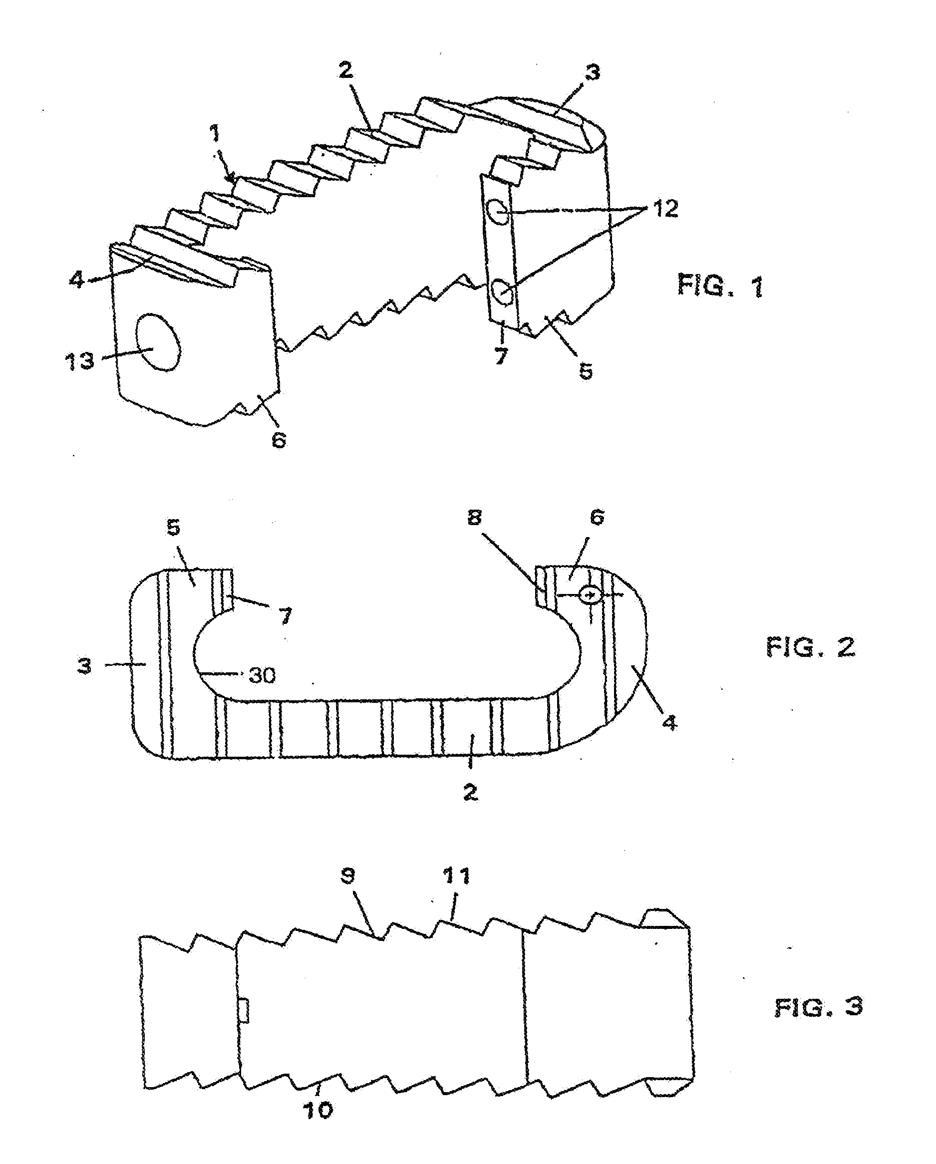
[0039]FIG. 1 shows in intervertebral cage 1 according to the invention. The intervertebral cage comprises a main wall 2 from which two return parts 3 and 4 project. The two return parts 3 and 4 are prolonged by a first end part 5 and a second end part 6 respectively. The two end parts 5 and 6 are approximately parallel to the main wall 2. The wall 2, the return parts 3 and 4 and the end parts 5, 6 delimit an inner cavity 30 in the cage, by prolonging the two end parts towards each other.

[0040] The two end parts 5, 6, are at a distance from each other and there is a clear gap between them. The clear gap extends along the direction of the length parallel to the main wall 2 over a length equal to 78% of the longest length of the inner cavity 30.

[0041] The two end parts 5, 6 face each other through a first end face 7 and a second end face 8. The main wall 2 is 3 mm thick. The thickness of the end walls is the same as the thickness of the main wall 2. The two return parts 3 and 4 are a...


PUM


Abstract

An intervertebral cage includes a thin main wall having two return parts at opposite ends of the wall. The wall has an approximately constant thickness. The return parts are extended by facing end parts having a gap between them. The wall, the return parts and end parts delimit an inner cavity. The gap extends parallel to the wall and has a length between 50% and 100% of the cavity length. The gap length is preferably between 70% to 90% of the cavity length.

Description

RELATED APPLICATIONS [0001] The present application is a continuation of pending U.S. patent application Ser. No. 10 / 276,712, filed Mar. 26, 2003, which is a U.S.C. § 371 application of PCT / FR01 / 01545 filed May 18, 2001, which claims priority to FR 00 / 06351 filed May 18, 2000. All of the foregoing are hereby incorporated by reference.FIELD OF INVENTION [0002] The present invention relates to an intervertebral cage designed to be placed between two vertebrae to restore and / or maintain the intervertebral space, to replace the intervertebral disk. After the cage or implant has been placed, the intervertebral space is filled with autologous spongy bone or adapted bone substitutes. This invention also relates to instrumentation for placement of the intervertebral cage. Finally, it also relates to a pair of intervertebral cages of this type. BACKGROUND ART [0003] Prior art has already described intervertebral cages, for example Stryker cages. These cages are parallelepiped-shaped, the bot...

Claims


Application Information

Patent Timeline
Patent Type & Authority Applications(United States)
IPC IPC(8): A61F2/44A61B17/58A61F2/00A61F2/28A61F2/30A61F2/46
CPCA61F2/442A61F2230/0082A61F2/4611A61F2002/2835A61F2002/30131A61F2002/30143A61F2002/30268A61F2002/30271A61F2002/30774A61F2002/30797A61F2002/30808A61F2002/30904A61F2002/4475A61F2230/0013A61F2230/0017A61F2/4455A61F2002/30261A61F2002/30593A61F2/44
Inventor HUPPERT, JEAN
Owner LDR MEDICAL SAS
Why Eureka
Try Eureka