Filter cleaning system and method

a filter and filter cleaning technology, applied in the direction of filtration separation, separation process, transportation and packaging, etc., can solve the problems of increasing the resistance to flow, and affecting the cleaning effect of the portion of the filter closest to the tubesh

Active Publication Date: 2008-01-31
PARKER INTANGIBLES LLC
View PDF13 Cites 17 Cited by
  • Summary
  • Abstract
  • Description
  • Claims
  • Application Information

AI Technical Summary

Problems solved by technology

Increased resistance to flow is undesirable because it inhibits fluid flow through the filters and / or requires more power to effect flow through the filters.
A known disadvantage of cleaning with known reverse pulse-jet cleaning systems is that a portion of the filter that is located closest to the tubesheet experiences little or no effective cleaning.
Other portions of the filter tend to be cleaned to excess and may become damaged.

Method used


Image

  • Filter cleaning system and method
  • Filter cleaning system and method
  • Filter cleaning system and method

Examples


Embodiment Construction

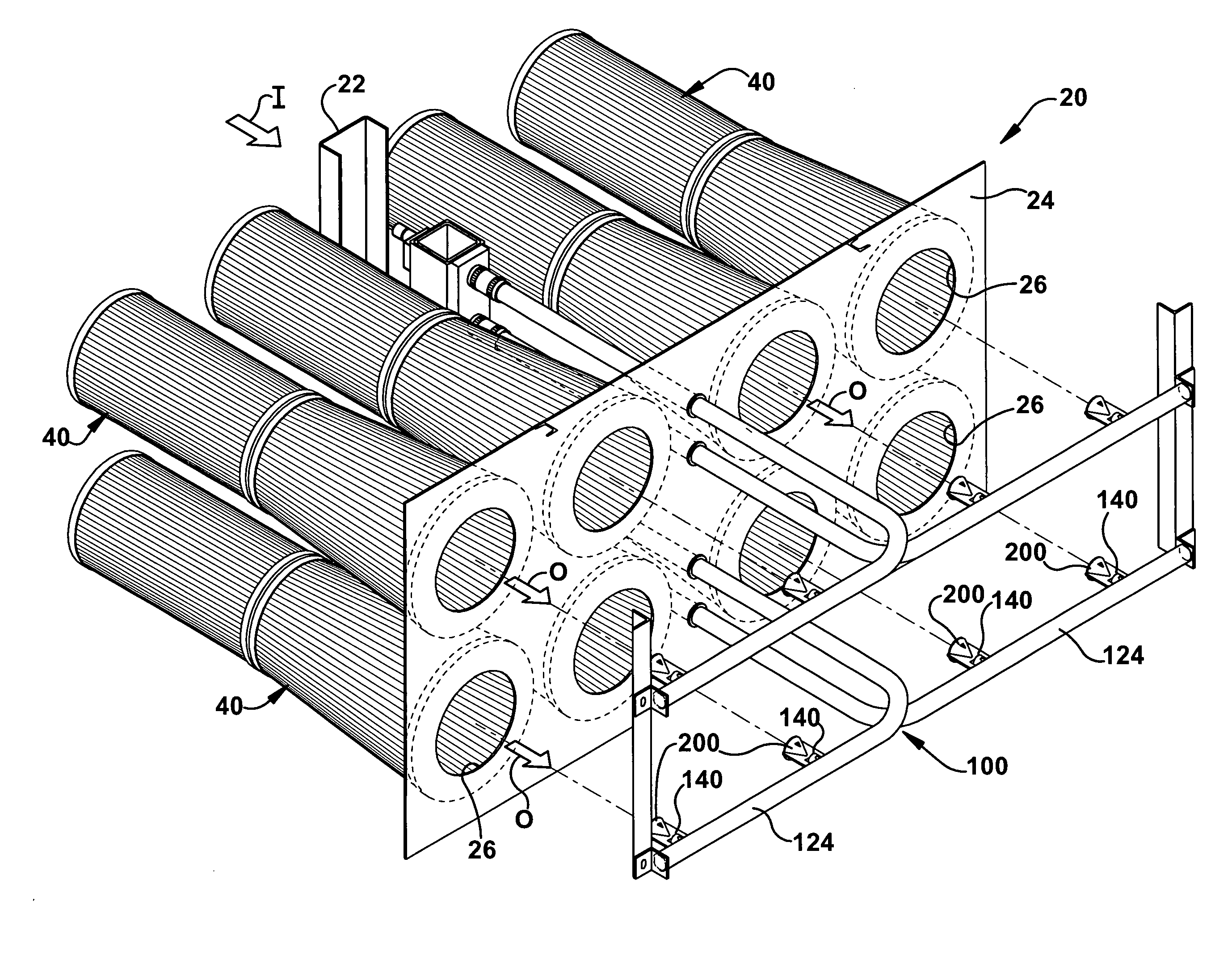
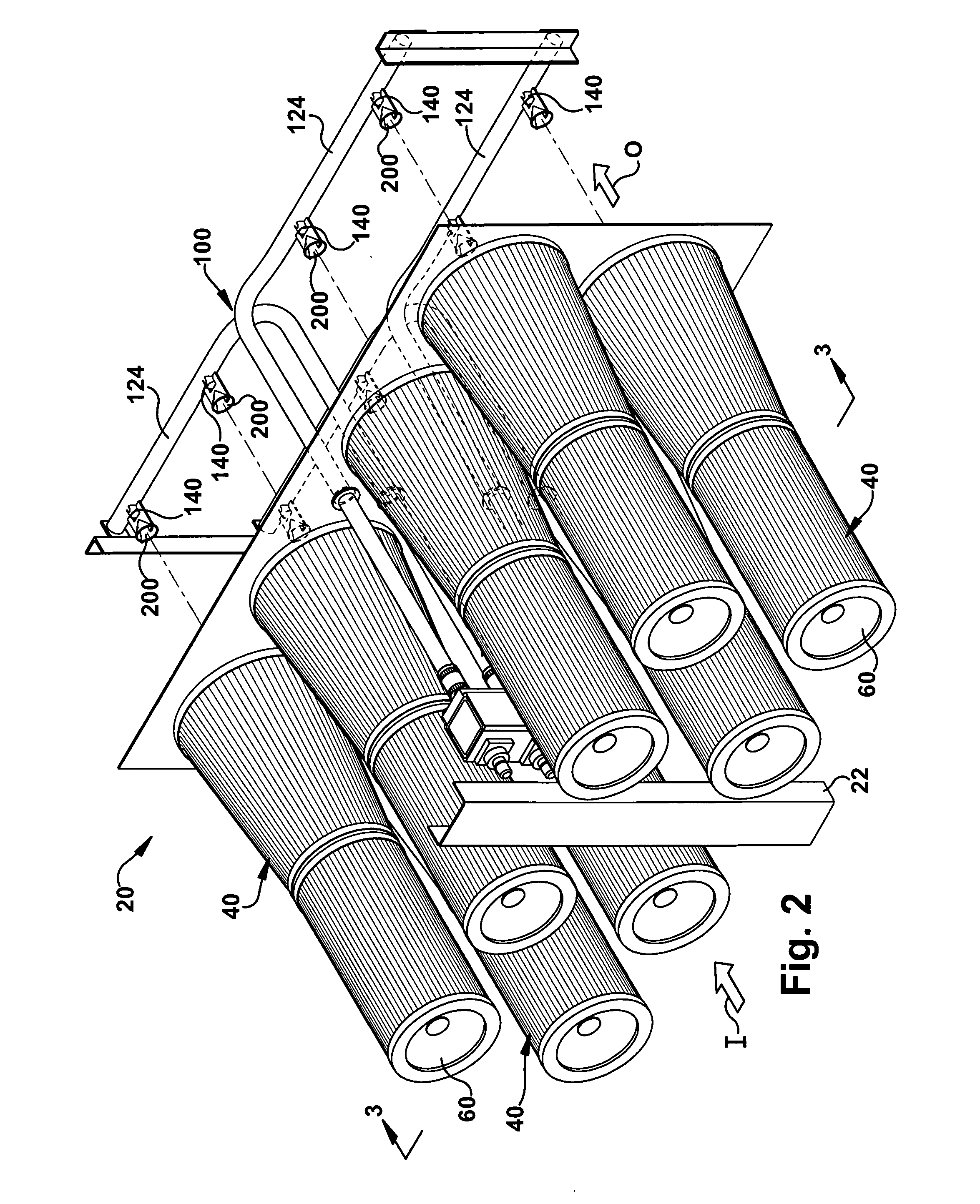
[0026]The system and method of cleaning a filter are described below by way of example and not limitation. The system and method are useable with a variety of filters. FIGS. 1 through 5 depict an exemplary fabric filter. The exemplary fabric filter illustrated is particularly suitable for use in a gas turbine intake filter system 20.

[0027]In FIGS. 1-2, particulate-laden fluid, such as air, is drawn into the gas turbine intake filter system 20 in the direction indicated generally by the arrow I. The gas turbine intake filter system 20 includes a housing (not shown) and a frame 22 that is used to support a tubesheet 24 and the housing. The tubesheet 24 includes a plurality of openings 26. The gas turbine intake filter system 20 includes a plurality of fabric filter 40 supported by the tubesheet 24. The filters 40 may be attached directly to the tubesheet 24 or indirectly connected with the tubesheet by intervening structure. The filters 40 are mounted adjacent to respective openings 2...


PUM

PropertyMeasurementUnit
time durationaaaaaaaaaa

Abstract

A cleaning system for a gas turbine inlet filter mounted to a tubesheet. The filter defines an upstream side at which particulates are separated from a fluid stream passing through the filter and a downstream side substantially free of the particulates. The cleaning system comprises a blowpipe for supplying a pressurized fluid. A one-piece nozzle is made from a tubular member having a substantially constant cross-section extending along the length of the member. The nozzle is permanently attached to the blowpipe at a first end portion. The nozzle is in fluid communication with the blowpipe to direct a cleaning pulse of the pressurized fluid from a second opposite end portion into the downstream side of the filter to dislodge particulates into the upstream side. An aspirator is formed in the nozzle at an upstream location spaced from the second end portion of the nozzle. The aspirator enables an additional volume of fluid to be delivered from the second end portion of the nozzle than is delivered from the blowpipe to the first end portion of the nozzle. A diffuser is fixed to at least one of the blowpipe and the nozzle. The diffuser directs a portion of the cleaning pulse to a proximal portion of the filter located adjacent to the tubesheet.

Description

CROSS REFERENCE TO RELATED APPLICATIONS[0001]This application is a continuation-in-part of Ser. No. 11 / 493,237 filed Jul. 26, 2006, which is incorporated by reference.BACKGROUND OF THE INVENTION[0002]1. Field of the Invention[0003]The invention generally relates to a system and method for cleaning a filter. In particular, the invention relates to a system and method for reverse pulse-jet cleaning of filters in an inlet housing of a gas turbine.[0004]2. Description of the Prior Art[0005]It is known that fabric filters are used to separate particulates from flowing fluids. The particulates tend to accumulate on and in the media of the filters over time. This particulate accumulation increases resistance to flow through the filters. Increased resistance to flow is undesirable because it inhibits fluid flow through the filters and / or requires more power to effect flow through the filters.[0006]In some known systems, reverse pulse-jet cleaning is used to periodically remove accumulated p...

Claims


Application Information

Patent Timeline
Patent Type & Authority Applications(United States)
IPC IPC(8): B01D46/04
CPCB01D46/0021B01D2275/201B01D46/04B01D46/0068B01D46/60B01D46/71
Inventor CLEMENTS, JACK THOMAS
Owner PARKER INTANGIBLES LLC
Why Eureka
Try Eureka