Self-fixturing pivoting actuator

a self-fixing, pivoting actuator technology, applied in the direction of arm assembly mounting, magnetic recording, arm assembly structure, etc., can solve the problems of increasing the physical size occupied by the storage capacity, increasing the cost of the actuator assembly, and increasing the physical size of the storage capacity, so as to improve the reliability of the pivoting actuator, easy to make, and low or no additional cost

Inactive Publication Date: 2008-01-31
ESGW HLDG
View PDF19 Cites 3 Cited by
  • Summary
  • Abstract
  • Description
  • Claims
  • Application Information

AI Technical Summary

Benefits of technology

[0016]It is another object of the invention is to provide a head stack assembly with fewer and less expensive parts while reducing overall manufacturing cost and increasing performance.
[0017]It is still another object of the invention to simplify the overall assembly operation of the head stack assembly.
[0018]It is still another object of the invention to reduce manufacturing tolerances yet improving drive reliability and robustness.
[0019]It is yet another object of the invention is to provide a head stack assembly that does not add mass to the disk drive system thereby achieving reduction in the access time of the magnetic heads to selected data tracks of the rotating disks.
[0020]It is still another object of the invention not to introduce foreign material into the disk drive. It will not outgas, corrode, wear, or fall off the suspension.
[0022]A novel application of geometrics, kinematics and semi-kinematic design principles are at the center of the present invention. Applying these principles while integrating parts serve the assembly and improves reliability of the pivoting actuator. The design principles provide the full natural tolerance and constraint balance for the assembly of parts. Parts they produce are easier to make, also, function much better as an assembly with zero-stress location.

Problems solved by technology

For the past several years, data storage methods has followed a tendency of escalating storage capacity while also shrinking the physical size occupied by its storage capacities.
Moreover, the threaded fasteners add increased parts and cost to the actuator assembly, while creating excessively constrained conditions that induce distortions and misalignment of significant parts within the assembly.

Method used


Image

  • Self-fixturing pivoting actuator
  • Self-fixturing pivoting actuator
  • Self-fixturing pivoting actuator

Examples


Embodiment Construction

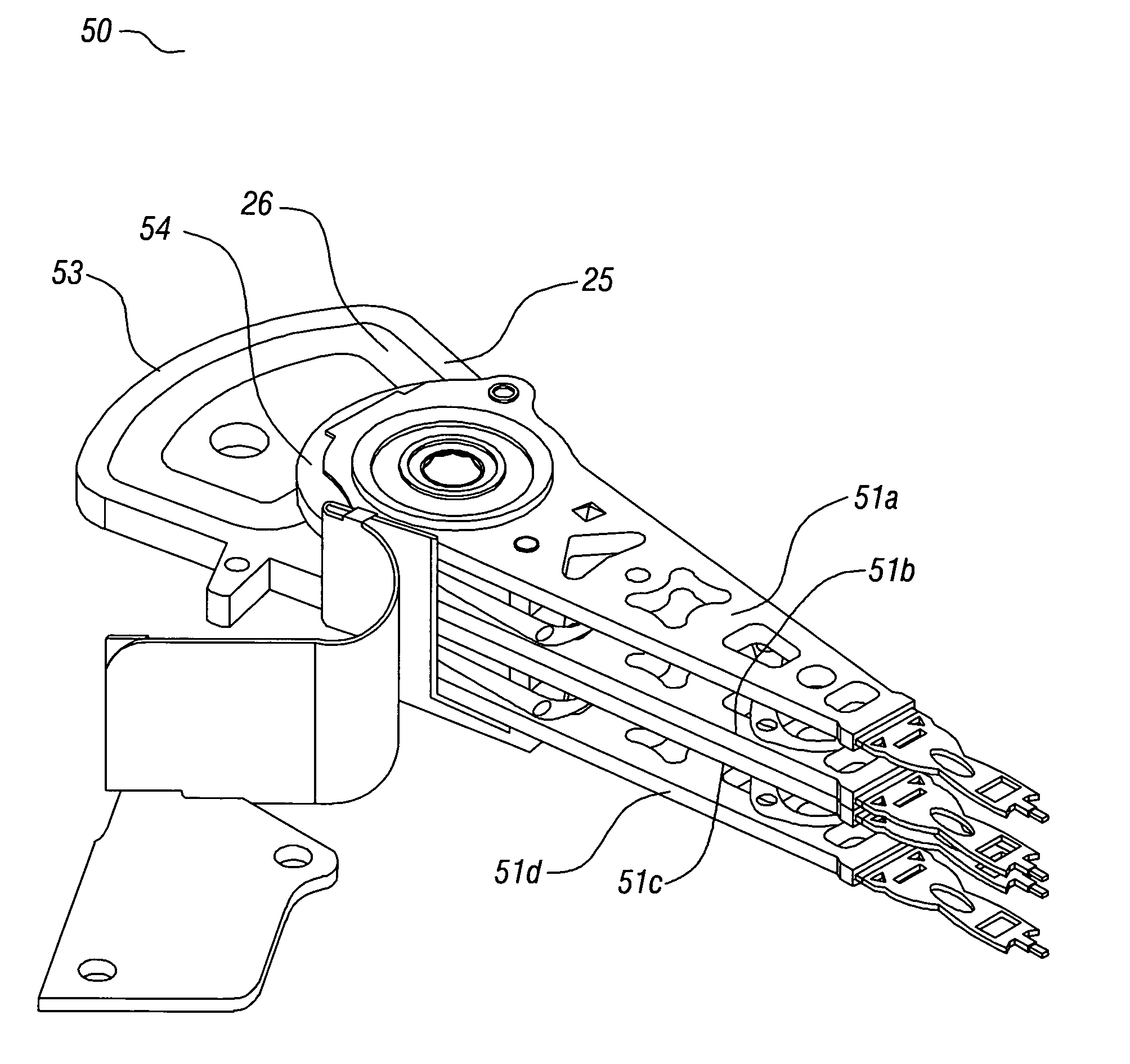
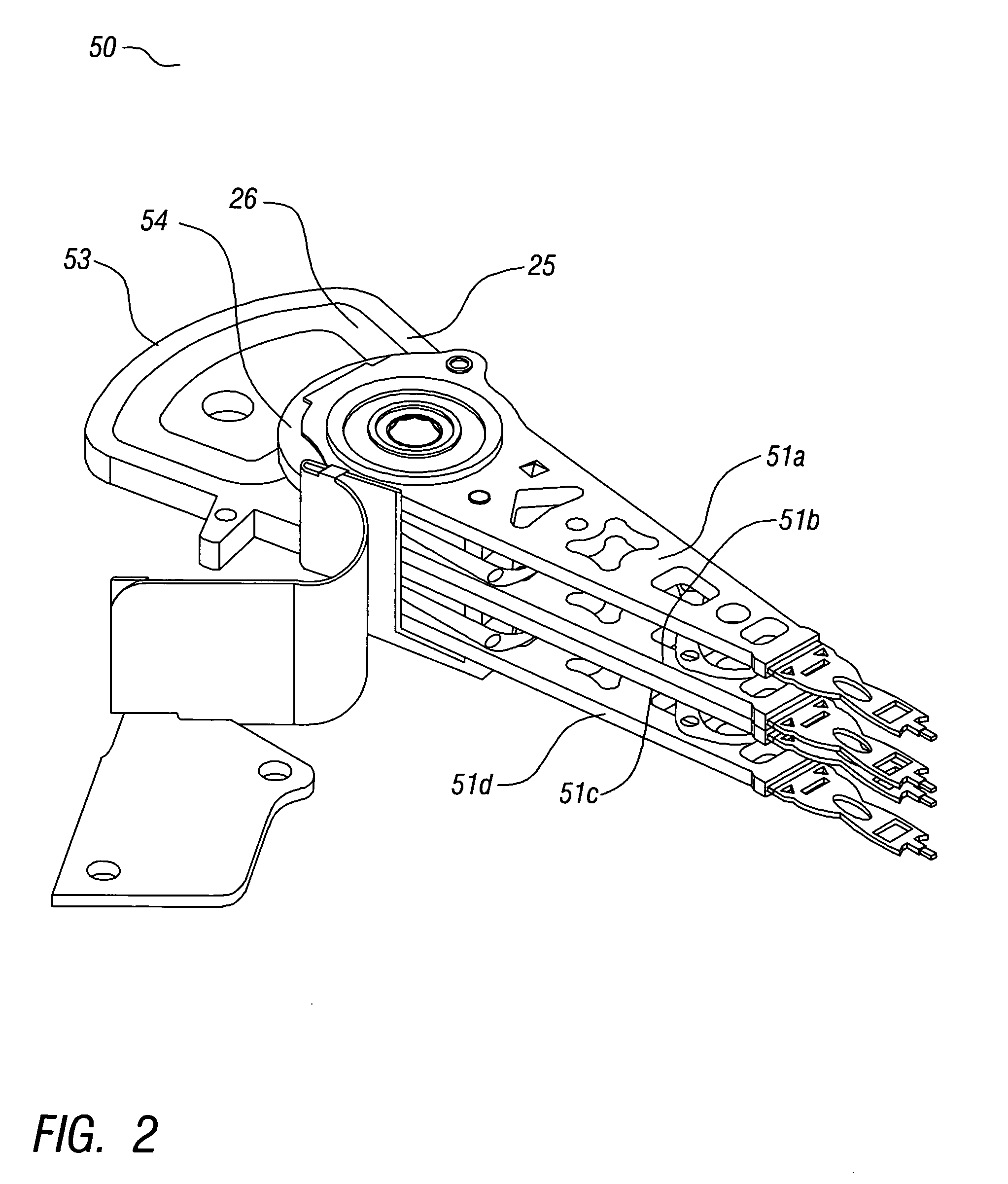
[0033]Referring now to FIG. 2 showing an exemplary design of a 2.5 inch, or smaller, head stack assembly 50 manufactured in accordance with this invention. In the embodiment shown, the head stack assembly is designed for a disk drive with two disks. The embodiment further includes head assemblies 51a, 51b, 51c and 51d with suspensions distally carrying heads used to read and write information on both sides of these two disks. The details of the four head arm assemblies are best illustrated in FIGS. 3c and 6-8. Referring now to FIG. 3c, a stacked sequence of the above multiplicity of parts are as follows: Starting from the bottom of the head stack assembly 50, there is head arm assembly 51d, a primary spacer 53, two more head arm assemblies 51c and 51b, a secondary spacer 54 and the forth head arm assembly 51a. The lower primary spacer 53 also incorporates a coil 55, which, along with a magnetic structure mounted to the drive base-plate (not shown), is used to rotate the actuator and...


PUM

PropertyMeasurementUnit
areaaaaaaaaaaa
forcesaaaaaaaaaa
forceaaaaaaaaaa

Abstract

A rotary actuator arm assembly for positioning a transducer over a data track of at least one rotating magnetic disk. The actuator includes self contained spacers with semi-kinematic mounting features to accurately locate and secure a set of self-aligning components, thereby eliminating azimuth alignment problems created by conventional assembly procedures.

Description

BACKGROUND OF THE INVENTION[0001](1) Technical Field[0002]This invention relates to a pivoting actuator used in a head stack assembly (HSA) for a magnetic disk drive, and more particularly, is concerned with improvements in manufacturing and assembly of actuator parts[0003](2) Description of the Prior Art[0004]The following four documents relate to methods dealing with improvements to a head stack assembly.[0005]U.S. Pat. No. 5,862,019 issued Jan. 19, 1999 to Larson discloses a disk drive actuator assembly adapted for assembly in one of several configurations from a single line of modular components without a manually supervised aligning step.[0006]U.S. Pat. No. 6,091,578 issued Jul. 18, 2000 to Stole. et al. describes disk drive actuator components made of composite material including two layers of fibers orientated in a perpendicular direction relative to each other.[0007]U.S. Pat. No. 6,002,551 issued Dec. 14, 1999 to Goss, et al, discloses a suspension attachment technique and a...

Claims


Application Information

Patent Timeline
Patent Type & Authority Applications(United States)
IPC IPC(8): G11B5/48
CPCG11B5/4813G11B5/5569G11B5/4833
Inventor RAYMOND, PETER J.
Owner ESGW HLDG
Why Eureka
Try Eureka