Low voltage stress power converter

a power converter and low voltage technology, applied in power conversion systems, dc-dc conversion, climate sustainability, etc., can solve the problem of limited voltage stress improvement, and achieve the effect of reducing current rippl

Inactive Publication Date: 2008-01-31
NAT TAIWAN UNIV OF SCI & TECH
View PDF9 Cites 22 Cited by
  • Summary
  • Abstract
  • Description
  • Claims
  • Application Information

AI Technical Summary

Benefits of technology

[0009]An object of the present invention is to provide inversion or rectification circuits for switching mode power converter which has reduced current ripple.

Problems solved by technology

Although the turn-off voltage is shared, voltage stress improvement is limited due to the leakage inductance energy.

Method used


Image

  • Low voltage stress power converter
  • Low voltage stress power converter
  • Low voltage stress power converter

Examples


first embodiment

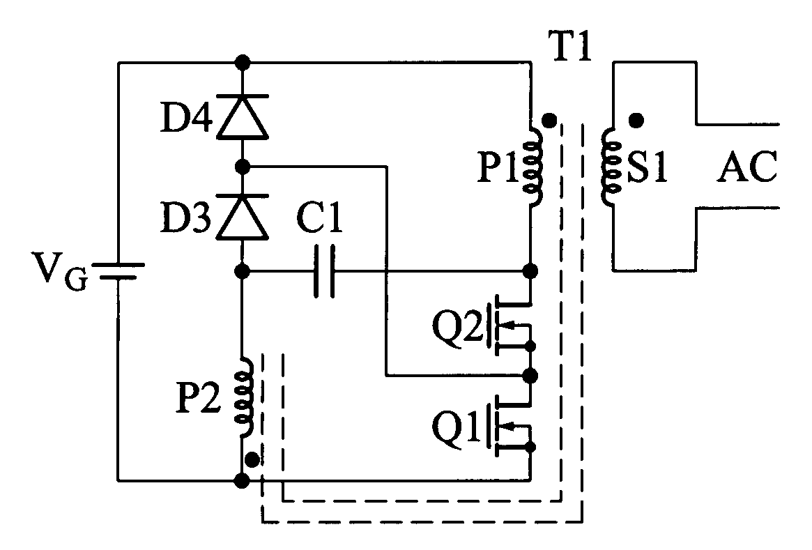
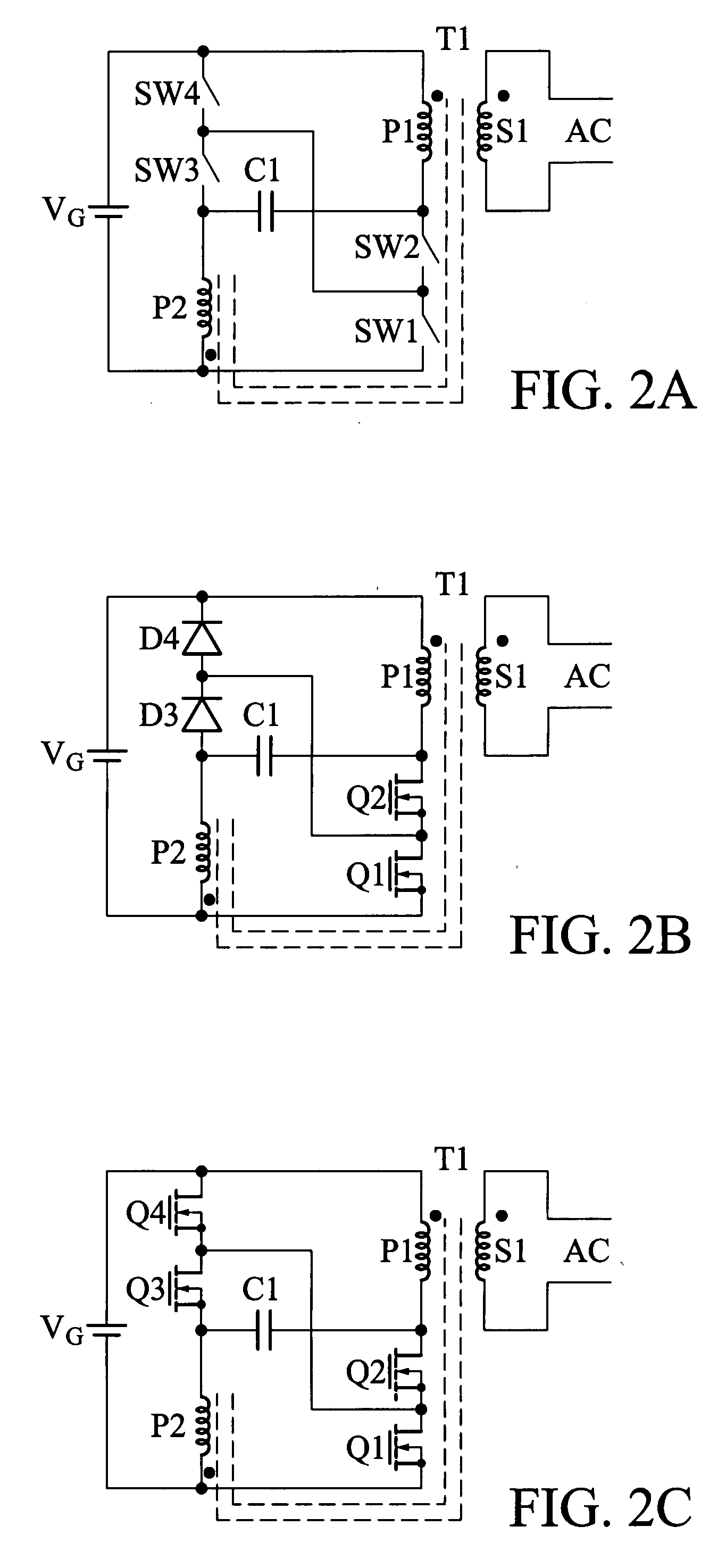
[0030]the present invention, A DC to AC inversion circuit is shown FIG. 2A. A voltage source, VG, provides a DC input to the inversion circuit. Two series circuits are parallel-connected with the DC input. The first series circuit includes primary P1 of transformer T1 and the first switch pair, SW1-SW2. The second series circuit includes the second switch pair, SW3-SW4, and primary P2 of transformer T1. The primaries P1 and P2 of transformer T1 have equal number of turns. Within each series circuit, there is a node at which point the respective switch pair connects with its respective primary. These nodes are coupled by capacitor C1. The center nodes of the first switch pair and the second switch pair are connected together. The circuit's AC output is provided at secondary S1 of transformer T1.

[0031]Operationally, the DC voltage, VG, is supplied to charge capacitor C1 via the two transformer primaries (P1 and P2) to the input voltage.

[0032]An embodiment to that shown in FIG. 2A is d...

second embodiment

[0039]the present invention, a DC to AC inversion circuit is shown in FIG. 3A. A voltage source, VG, provides a DC input to the inversion circuit. An input inductor, Lin (represented the parasitic inductor or an external inductor), is inserted between the DC input and two paralleled series circuits. The first series circuit includes the first primary pair (P1-P2) coupled in series through a first switch pair, SW1-SW2, while the second series circuit includes the second primary pair (P3-P4) coupled in series through a second switch pair, SW3-SW4. The first primary pair (P1-P2) and the second primary pair (P3-P4) are coupled to the same transformer T1 with equal number of turns in each primary. Within each series circuit, there are two nodes at which points the respective switch pair connects with its respective primary. These nodes are coupled by capacitor C1 and C2. The center nodes of the first switch pair and the second switch pair are connected together. The circuit's AC output i...


PUM


Abstract

A circuit used to convert a DC input to an AC output comprises a pair of series circuits, one or two capacitors, and one transformer. Each of the series circuits is in parallel with the DC input and comprises a pair of series-connected switches and at least one transformer primary. Each capacitor couples the two series circuits, and is attached to each series circuit at a node between the respective transformer primary and switch. The center nodes between two series-connected switches are connected together. At least one secondary on the transformer provides the AC output. Optionally, multiple transformers may be utilized. Similar topologies may be used for rectification instead of inversion.

Description

BACKGROUND OF THE INVENTION[0001]1. Field of the Invention[0002]The present invention relates to pulse-width modulation power conversion circuits which implement current ripple reduction and lower voltage stress on both of the active and passive semiconductor switch with minimum component count.[0003]2. Description of the Related Art[0004]Current ripple reduction has been implemented in a variety of circuits, some of which are described in U.S. Pat. No. 5,038,263, issued on Aug. 6, 1991, to Joseph Marrero and Christopher Peng. The voltage stress on the switch is the sum of the input voltage, the transformer reset voltage, and the turn-off voltage spike introduced by the leakage inductance. By series-connecting two switches, a ripple steering circuit has been invented in U.S. Pat. No. 5,786,990, issued on Jul. 28, 1998, to Joseph Marrero. Although the turn-off voltage is shared, voltage stress improvement is limited due to the leakage inductance energy.[0005]Therefore, it is desirabl...

Claims


Application Information

Patent Timeline
Patent Type & Authority Applications(United States)
IPC IPC(8): H02M3/335G05F1/10
CPCH02M3/33569Y02B70/1475H02M3/33592H02M3/33576Y02B70/10
Inventor LEU, CHING-SHAN
Owner NAT TAIWAN UNIV OF SCI & TECH
Why Eureka
Try Eureka